Heater Air Conditioner System |
 |
| TITLE |
+ |
- |
| FILE NAME |
+ |
- |
| DATE |
+ |
- |
| POSITION |
+ |
- |
|
|

Replacing the blower motor572 viewsThis is a 6 page pdf with regards to replacing the HVAC blower fan and the associated fan speed module in a LHD North America spec LR3. The fan can be replaced from below and it is not necessary to pull the dash apart.
|
|

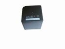
Front Blower R16 relay, part number YWB500060473 viewsThis is the front fan relay located in the engine compartment fuse box. It should be replaced and installed new when a new fan is installed.
|
|

Pollen Filter Replacement in HVAC System499 viewsThe attached single page doc includes links to pictures of the procedure to replace the "air" filter behind the passenger side glove box related to the Heater AC system.
Part numbers are provided for both Land Rover and Mann filters, both the activated carbon type and the non charcoal filters.
|
|

Front Heater Doors Description and Operation1357 viewsThis 6 page pdf shows with coloured drawings the air flow thru the front heater as well as discusses the operation of the various air flow doors.
|
|

Cooling System - Description and Operation 4.0L and 4.4L petrol engines 5 pages1009 viewsThis is a 5 page pdf that provides some insight into how the coolant flows thru all the hoses. Of interest is the paragraph,(page 3/5), that attempts to explain how and why the thermostat is designed to open at different engine operating temperatures - in brief, the reason for the spaghetti tangle of small hoses on the top of the engine.
There is also reference to an engine oil cooler that I gather cools something I think related to a supercharger, if fitted.
|
|

Thermostat Housing LR005631527 viewsWhen the time comes to install a new thermostat, consider installing the whole housing instead.
Advantages are the thermostat is correctly installed, (not as simple as it should be); you get all new plastic and that is important, plus a new coolant temperature sensor and also a new heater coolant bypass valve, the secret part no one realizes is also within.
The cost of the whole assembly is not much more than the cost of a factory thermostat and the effort to replace all is not as difficult as it might seem.
|
|

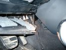
Air Conditioner Drain Hose on Drivers Side (LHD)2256 viewsThe corrugated rubber bit above and to the right of the gas pedal is the drain hose that goes down thru the carpet and floor sheet metal.
While it is bit hard to figure out from the jpg above, there is a rubber "strap" attached to the top of the corrugated hose that one uses to pull on to drag the hose up back around the black plastic heater "pan" drain. The same drain hose arrangement is on the other side as well.
One could I suppose run a plastic snap tie around the vertical pull strap if one was concerned about the hose slipping off again. See also the other jpg sketch which is from the Land Rover manual.
|
|

LR3 Air Conditioner Drain Tubes behind centre console2091 viewsThis shows the two air conditioner drain tubes located left and right under the radio stack.
The tube on the left side, (steering wheel side, LHD), disattached itself and the carpet on the floor under the gas pedal etc became soaked. I think rain water from outside that comes in the outside cowl vents also exits via the tubes as I first noticed the carpet was wet after parking outside during a big rain storm.
It was relatively easy to slide up and reattach the rubber hose that runs from the rectangular shaped plastic discharge hole(s) of the heater "pan" down along the transmission hump area and thru the floor pan. There is a hose on each side of the transmission hump, but only one hose had let go on my 3. The rubber hoses just slide over the rectangular plastic openings of the two heater housing drain outlets.
To get at each drain hose, remove the vertical sort of triangle carpeted piece below each side of the radio stack. The triangles of carpet will just pull away as each is held on with those metal U clips Land Rover so likes. Dislodge each triangle at least sufficiently to get ones hand in to slide the rubber hose back on.
You will rarely see AC water on the ground as the front drains pour onto a metal underside protection skid plate and the rear drain onto the top of the left rear muffler.
|
|

Air Distribution and Filtering Systems2045 viewsThis is 3 page pdf with coloured drawings of the air distribution ducting for the front air system.
Also included is a sketch of the pollen filter location within the front heater ducting. Note that two types of filters are available: a) the cheaper dust/pollen filter and b), the activated carbon filter that removes smells from the air. Installing the more expensive activated carbon filter means you never smell a cattle truck or chicken farm again. It really works.
|
|

Air Conditioning and Heater Control Components2376 viewsThis is a 21 page pdf that really explains how the air system is supposed to work. Discussed are the exterior ambient air sensor, where and how it operates; the interior temperature sensor as well as humidity sensor.
|
|

Air Conditioner Specifications 4.4L V81538 viewsThis 2 page pdf is just the specifications for the AC system. The refrigerant type is R134A.
Note that when topping the system up, it can be a good idea to include some of that ultra violet light dye that will glow to show leaks and loose fitting.
|
|

Rear Area Climate Control System1140 viewsThis 14 page pdf describes how the rear heating AC system is supposed to operate in conjunction with the front system.
The air transfer ducts are shown as coloured sketches as is the air flow within the rear blower setup.
|
|

LR3 Air Conditioning High Line electrical wiring diagrams1447 viewsThis 7 page pdf shows the wiring for the Heater/AC both front and rear.
|
|
|
|
|
|
|