LR3 Air Suspension fuse 35P ECU Manual Shut Off Switch |
 |
| TITLE |
+ |
- |
| FILE NAME |
+ |
- |
| DATE |
+ |
- |
| POSITION |
+ |
- |
|
|
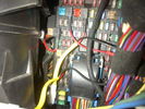
Fuse Panel showing F35P Add A Circuit installed1230 viewsFive amp fuse F35P is located towards the top left in this jpg. The other three Add A Circuit devices are for other items - powering my cell phone base etc.
Note the orientation of the Add A Circuit as this matters. Also one can just see a red tab sticking out from behind the device. The red is the conductor crimp end of a narrow 2.8mm male spade type connector that inserts into one of the "fuse" slots.
|
|
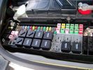
Picture of the engine compartment fuse panel5752 viewsEngine compartment fuse panel located near the battery. This is where F3E, (5 amp), F26E, (20 amp), Fuseable link 10E, (60 amp) and Relay 7E, the now upgraded 70 amp air compressor motor relay, part number YWB500220, (E is for Engine compartment fuse box), are all located. Fuse F35P, (5 amp), is inside the Passenger compartment behind the lower glove box door.
To keep the suspension from going down to the stops when driving, (or parked), it appears that it is only really necessary to remove F26E to depower the exhaust valve and generally keep all the valve block solenoid valves in a closed position trapping whatever air is within the air springs. F3E gets its power thru F26E, so when F26E is removed, the F3E circuit is automatically de-powered. F35P is more interesting in that battery power goes thru the ignition switch and F35P and then into the air suspension control unit. Apparently however, if F26E is removed, removing the F35P is not needed even when the engine is running.
With all fuses still in, if you have a problem, in practice, ideally, the compressor still works and will raise the 3 to an appropriate height. If so, one can then shut the engine off and allow the computers to go to sleep and then you remove the fuse(s). In actual practice, it seems that one need only pull the F26E fuse and can do so with the engine running. All the same, one might consider that the 3 is first a mobile computer, and secondly a 4x4. Computers prefer to go to sleep before the plug is pulled on them, however given that F26E circuit is always alive, then the computer never sleeps. With the fuse(s) pulled, and if you are still up, you can now be a 4x4 instead of a low rider. The whole purpose of the fuse pulling exercise is to depower the one and only system exhaust valve that is physically located within the compressor unit, (to keep it from opening), and secondarily to keep closed the four air spring solenoids within the block valves. This also shuts the air compressor down and stops the air compressor from making air even if the compressor is still good. That is why you initially need the fuse(s) in to allow the compressor to make air if it can.
|
|
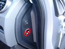
Air Suspension ECU Fuse 35P cut off switch.3802 viewsThis shows the SPST rocker switch mounted in the blank plate installed in lieu of a manual passenger side air bag shut down switch - now automatic via passenger seat pressure switch. Fuse 35P (5 amps) is located in the interior fuse box behind the lower glove box and protects the ignition power supply to the Air Suspension ECU. When the SPST switch is moved to the OFF position, the RAISE /LOWER switch on the centre console is not powered, and hence does not function. As such, some signals from the wheel height sensors and CPU are ignored. By itself however, removing F35P will probably not stop the 3 from self dropping, particularly after the engine is turned off.
Fuse F3E, (5 amps), located in the engine bay fuse box by the starting battery protects the circuit that provides feedback to the Air System ECU indicating that the Compressor Relay has successfully operated and that the Air Compressor is or should be operational, can also be removed, (but is probably not totally necessary), as it gets its power thru F26E. Hence Fuse F26E, (20 amp), also located in the engine compartment fuse box is the fuse that must be removed. This fuse protects the circuit that provides full time battery power to the Air System ECU. When in place, current thru the fuse powers the periodic re-levelling action, (usually lowering a bit with that brief air release noise), that often occurs when the vehicle is parked and the engine is off.
Removing F26E fuse will stop the auto levelling action and also inhibit any other down to the stops signals, (engine running or not). When F26E is removed, no power can flow thru to F3E, hence removing F3E is more for insurance than an absolute requirement. The same with F35P, removing F26E removes primary full time power from the Air Suspension ECU, and hence removing the F35P fuse should not really be required either as long as F26E has been removed.
|
|
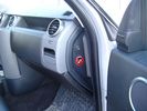
Air Suspension ECU Fuse 35P Shut Off Switch2623 viewsA more distant view of the shut off rocker switch in the ON position which is the normal position for when all is working as Land Rover intended.
Ideally, (but not totally necessary), the F35P circuit should be powered or de-energized after the various computers have gone to "sleep".
Similarly, removal of the F26E or F3E fuses is preferable after the computers have all gone to sleep but it appears that no real damage will be done if the fuses are removed while the system is energized. Pulling F26E is the main full time fuse that powers the air suspension computer. As such, once F26E is removed, pulling F3E is not really required.
Power for the compressor goes thru the 60 amp fusible link and relay, however control of the relay is via the air suspension computer so depowering the air suspension computer effectively depowers the air compressor and the internal exhaust valve relay/port.
|
|

Underhood Fuse and Relay Box drawing 3041 viewsShows the various fuse and relay locations. Fuse 3E, (5 amp), and Fuse 26E, (20 amp), as well as upgraded 70 amp Relay 7, part number YWB500220, locations are displayed. Relay 7 sends battery power to the compressor from the 60 amp fusible link called up as 10E. Fuse 26E is what provides full time always on battery power to the air suspension ECU and hence powers the auto level wakeup when the vehicle is shut down and say parked for the night. Removing F26E is the primary method to disable the air suspension system; Removing F35P is more if you want to experiment with it from inside.
I found it useful when I had a suspension problem, (actually a wheel alignment problem picked up by the steering wheel angle sensor), that only showed itself on the highway but allowed for no trouble light driving in the city. This was because in the city, the steering wheel was always in motion and rarely was the vehicle driven in a near straight line for very much distance.
|
|

Air Suspension Wiring Sheets3025 viewsThese two sheets show the wiring and fuses related to the operation of the air suspension system. Fuses F3E, F26E, and F35P are shown as well as the interior up down switch and the wheel height sensors.
As with all pdf's, you can rotate them to view plus download and or print out as you wish.
|
|

Air Suspension System Parts, Layout, and Operation7015 viewsThis 22 page pdf gives a pretty good description of how the system is supposed to work, plus shows the various parts and the electrical including fuses and relays etc. Of the files here, this is the most useful.
As with all the pdf's here, you can download and print it out.
|
|
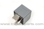
Air Compressor 70 amp replacement relay1384 viewsThere is a software update, 09 April 2010, LTB00270, for the compressor which reduces the shut down pressure to about 205 psig (14 bar). The update is usually done when changing to a new compressor and also includes replacing the R7 relay in the engine compartment fuse box, 07 DEC 2010 LTB00331.
The newer grey case coloured relay, part # YWB500220, shows to be rated at 70 amps, (the relay, not the compressor), however the previous black case coloured relay also indicates 70 amps.
Both the new and replaced relay show on their wiring diagrams to have a parallel voltage spike resistor, (probably 560 ohms), across the coil terminals, #1 and #2. This means one does not just replace the relay with any four prong 70 amp ISO sized relay that one happens upon.
One presumes the grey relay is either upgraded or just being installed for good measure. The relay is common on Ford Fiesta for the seat heater relay, Ford part number 5M5T 14B 192 EA; also Volvo, part number 30765034. The Tyco part number moulded on the grey body is V23136-J4-X62.
|
|

PDF of Mini Fuse data re LR3 / Disco 3 fuses.1846 viewsThis is just a data sheet regarding the MINI fuses that are common in the 3.
|
|
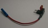
Littelfuse Mini Add-A-Circuit FMH200BP and OFH0200ZP1610 viewsFound this jpg somewhere on the forum - others are using them as it is a good way to tap the fuse box to add a fused circuit, or in this case, to modify a circuit to add a switch such that the fused circuit is switched. In my SmoothTalker gallery, there is a PDF from Littelfuse specifically related to this Add-A-Circuit device.
Before you install the Add A Circuit for any application, take an ohm meter and trace out the circuit path of the two pair of slots that fuses could insert into. The path is more complicated than one might first think. As such, the orientation of the fuse holder in the socket may matter depending upon the application. If the application is a circuit diverter, (as the F35 mode is), as opposed to a mere accessory adder, orientation matters.
|
|

Add A Circuit Littelfuse Data sheet2264 viewsThe switch connects to what Littelfuse brand calls an Add-A-Circuit model FMH200BP which is an adapter that plugs in place of a Mini fuse and then has space for two Mini fuses, (original and a second one). In this install, only the original 5 amp fuse was used - adapter was so as to route power from fuse box thru fuse, then rocker switch, and then back to fuse box.
Before you install the Add A Circuit for this application, take an ohm meter and trace out the circuit path of the four slots that fuses could insert into. The path is more complicated than one might first think. As such, the orientation of the fuse holder in the socket matters for this application - that is for a circuit diverter, rather than accessory adder.
|
|

Steering Column detailing Steering Angle Sensor1480 viewsItem 2 in the picture on page 1 of the 9 page pdf shows the location of the steering wheel sensor. Page 5 of the pdf has a paragraph describing the operation of the sensor. When the steering wheel does not point the same direction as the real wheels, then the computers can put the 3 into safe mode and down goes the suspension. See also the 17 page pdf on the Anti Lock and Traction Control pdf.
|
|

Anti Lock and Traction Control description and operation.1968 viewsNote on page 6 of this 17 page pdf the significance of the Steering Angle sensor mounted on the steering wheel shaft. The paragraph regarding the plausibility check as related to the brake pedal being not depressed is why the clean operation of the second set of contacts on the brake switch matters so much.
|
|
|
|
|
|
|