FASKIT Air Suspension Installation |
 |
| TITLE |
+ |
- |
| FILE NAME |
+ |
- |
| DATE |
+ |
- |
| POSITION |
+ |
- |
|
|
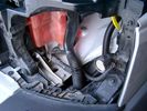
19 mm wire, (tubing), loom rising from below at left headlight652 viewsFrom the FASKIT panel, five air lines fit in the 3/4" (19mm) wiring loom and feed to the front air valve block located behind and under the right front fog light.
|
|
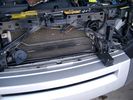
19mm wiring loom in trough behind bumper and in front of rad790 viewsThe 19mm wiring loom is large enough that a maximum of six 6mm air lines can be fished thru as required. The loom runs from the FASKIT panel located in the engine compartment behind the left front headlight, down and across in front of the rad and then down to the front axle valve block located behind and below the right fog light.
|
|
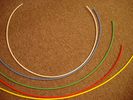
6mm Heat Shrink colours 362 viewsI decided to colour code the tubing so I used 6mm electrical heat shrink.
As there is no apparent colour coding re the 3, I tried to emulate the P38 coding; #1 LR red, #2 RR blue, #3 LF yellow, and #4 RF green. This was not doable as both left side air springs have green coloured tubing coming off the top of the front and rear air springs. I therefore arbitrarily chose the Left Rear to be red; Left Front green; Right Front yellow; Right Rear blue; and for the air compressor supply line, White coloured heat shrink. Since two new lines tie into each air spring line, I made the line between the air spring and the FASKIT, a single solid colour, and the line from the FASKIT to the valve block, White, plus the related appropriate solid colour.
|
|
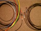
6mm PA12 grade nylon tubing with heat shrink applied 538 viewsShows some of the 6mm air line with heat shrink applied to one end of tubing. Shrink will be applied to the other end once field cut to length. These four tubes, each about 20 ft (6m) long, feed to the rear. Re the front air lines, (not shown), four additional lengths, each about 10 ft (3m) long, are required plus one more 3 metre length for compressor air. The 6mm tubing is a Nylon product specified as PA12. There is also a very similar Transport grade PA11 material, however it seems that PA12 is the more common Transport grade now in use. Also the applicable DIN standard seems to be both DIN 73378 and DIN 74324 for the nylon tubing. The working pressure of the 6mm tubing is about 27 Bar and bursting 82 Bar @ 20C. This is for the 1mm nominal wall thickness material, (4mm ID, 6mm OD).
|
|

Air System Schematic with parts identified.1363 viewsAir system block diagram with components numbered and identified.
|
|
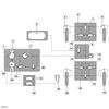
Block Diagram of Disco 3 / LR3 Air Suspension System.1539 views
|
|
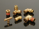
Detroit Fluid DOT air line fittings716 viewsThe picture shows the internal ferrule that is characteristic of the DOT / TUV accepted fittings for highway vehicles. Most often these fittings are metal however the Land Rover John Guest 6mm straight connector is all plastic and has the internal ferrule.
|
|
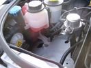
Empty space in NAS LR3 for location of FASKIT panel595 viewsThe empty space is available as the North America Spec gasoline engine LR3's do not have the Fuel Burning Heater installed. The air lines from the four air springs and the air tank will appear to rise up from under the headlight assembly. The lines to the front block valve assembly located behind the front right fog light will sort of run within the bumper across the front of the radiator down into behind the righthand fog light. The rear lines somewhat follow the path of the existing air feed line from the front valve assembly to compressor. Rather than be located between the left front fender liner and left metal wing however, the four lines will feed thru the empty wing space inside and above the wheel well arch and exit down by the left front mud flap. From there, the lines run along the left frame member above the air tank and then parallel the frame over top the compressor to the top of the rear left air spring where the rear air block valve assembly is located.
|
|
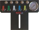
FASKIT air panel unmounted836 viewsThis is the manual air valve panel that is mounted in the "empty" space where the FBH normally resides. The gauge reads to a maximum of 25 Bar. The air tank relief valve is set just over 16.5 Bar (240 psig); the front air springs run maybe 9 Bar, (130 psig) and the rear, somewhat less, perhaps between 5 and 8 Bar. (70 to 115 psig). Max theoretical air spring pressure at full compression due to a big bump and full gross is approximately 27 Bar (390 psig).
|
|
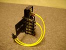
FASKIT on end view 859 viewsEnd and rear view of the FASKIT. Yellow lines are as shipped for hooking to the air supply; one line to valve/filler and other is to gauge. I will modify the arrangement to delete one of the yellow lines such that gauge line plugs into where the second yellow line is right now,(will be only one yellow tube), and then the air source line will plug into the port controlled by the valve, (hidden in this view but visible in other view). When white valve is in the ON position, gauge will read air source pressure, and be available to supply air to any of the selected four air springs. When valve is closed, the gauge will show individual air pressure in each of the air springs when a jumper is run between the gauge Schrader valve and the appropriate air spring Schrader valve.
|
|
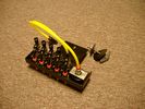
FASKIT rear showing gauge.918 views
|
|

John Guest (LR part # STC8580) push in straight 6mm tubing to tubing connector727 viewsThis picture is similar to the air suspension pneumatic fitting union that Land Rover sells as replacement part # STC8580. This is a 6mm OD tubing size push in to install straight tubing to tubing fitting. The STC8580 comes with what are called "Collets" at each end that cover up the press to release feature underneath. See the John Guest web site www.johnguest.com under the Pneumatics section and also in Downloads for their catalog for install and remove instructions.
The actual fitting that Land Rover provides has an interior 4mm OD ferrule that slips inside the 4mm ID of the nominal 6mm tubing. Hence the fitting depicted and part number are not actually correct. I have not yet been able to obtain the John Guest part number for the LR fitting.
The fittings that show in this doc are what I call food service fittings rather than transportation or Air Brake fittings. The part LR sells, (STC8580), is the Air Brake type for transportation.
|
|
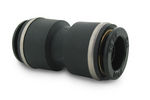
John Guest DOT all plastic fitting714 viewsThis is a picture of the John Guest DOT all plastic union. If you look closely, you can see the DOT imprinted in raised letters on the end of the fitting. This is of a 1/4" connector rather than the 6mm that the 3 requires.
The picture is similar to the air suspension pneumatic fitting union that Land Rover sells as replacement part # STC8580. This is for 6mm OD tubing size. The STC8580 comes with what are called "Collets" at each end that cover up the press to release feature underneath. See the John Guest web site www.johnguest.com under the Pneumatics section and also in Downloads for their catalog for install and remove instructions.
The actual "air brake spec" fitting that Land Rover provides has an interior 4mm OD ferrule that slips inside the 4mm ID of the nominal 6mm tubing. I have not yet been able to obtain the John Guest part number for the LR fitting, only the LR part number. This part number was generated for the RR Classic air systems.
|
|
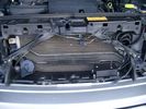
Plastic cover and Box back on in Front of Radiator 636 viewsThe wiring loom is below the cover - nothing is crushed or distorted and all fits back together OK. The black plastic box with the DPDT, (centre OFF), toggle switch is to tie the battery maintainer to each of the two batteries per the Traxide Dual battery install. I can also get power to the power door locks if all fails.
|
|
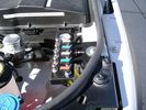
View from front left side looking towards rear aux battery compartment under cover 642 viewsAs there is no Fuel Burning Heater in the NAS V8 petrol vehicles, there is space available to install the FASKIT panel here. The piping is such that each air spring can be isolated from the air system and then filled one at a time manually via the Schrader valve. There are five Schrader valves and five shutoff valves. The fifth valve nearest the gauge controls air from the compressor, and can provide fill up air via a jumper fill line assuming the compressor is still operational.
|
|
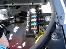
View of mounted panel from front left corner732 viewsI drilled a hole for the supplied 6 mm tie down toggle bolt in a flat portion of the wing on which the panel sits. I inserted a 50 mm flat rubber washer between the wing metal surface and the underside of the black painted panel plate; also a 40 mm flat rubber washer between the supplied fender washer and the metal plate - just seemed like a good idea so surfaces mate well even if wing metal not completely flat.
|
|
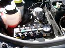
View of mounted panel from front left side872 viewsNote that all valve handles are shown in the OFF position, (the trouble position). In this case, the air that is in the air springs, (if any), is trapped in there - that is the valve blocks cannot vent whatever air is already in the air springs as the air lines between the springs and respective valve blocks are closed off by the FASKIT valves. In operation, there may be only trouble with one air spring, (perhaps a wheel height sensor), and as such, only one valve would need to be closed. If there was complete air compressor failure, then all valves would be closed and then as required, each spring could be manually filled from an outside clean dry oil free air source.
|
|

Voss B203 Fitting Install954 viewsNote on the first page, the reference to DIN 73378 and D74324 and also PA11 and PA12 material when referencing suitable spec nylon (polyamide) air line for motor vehicles. I think some of the 6mm fittings used on the 3 for the valve blocks are the System 203 type and called up as Land Rover part number RQC 000030. The Voss part number is I believe 5 2 03 11 01 00.
|
|
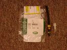
Voss System 203 connector 6 mm for valve blocks 900 viewsThis is Land Rover part number RQC000030, the Voss fitting for the axle valve blocks. I think it is a Voss System 203 6mm fitting, Voss part number 5 2 03 11 01 00.
The parts bag comes with the white plug inserted in the brass threaded bit with what is called the brass cutting ring placed on the tip of the white plastic plug. The idea is that one screws, (M10 x 1 thread), the brass insert into the appropriate hole with the white plug still in the brass insert. Once the brass is tight, (12 mm wrench), then the white plug is pulled from the assembly leaving the cutting ring down inside and under. One then pushes in the 6 mm tube end about 20 mm or so and the tube slides down thru the brass cutting ring, (2 internal sloped one way cutting ridges). When the tube is in far enough, one pulls upwards a bit and the ring cuts into the plastic such that the tube will not pull out. To remove tube, one unscrews the brass nut and all comes out, sort of like I have shown with the short piece of 6mm tubing. The white plug is a throwaway item upon install of the tubing.
|
|

Voss System 203 Connector cut thru, (similar to in valve block).676 viewsThis is a cut thru of a Voss System 203 connector. The top third of it is similar to the connector that holds the three 6mm plastic tubing lines into each of the front and rear valve blocks.
I say top third, as per the other pictures, the 3 has a Voss assembly that threads into the plastic of the valve block, whereas in the cut thru above, the Voss brass assembly is threading into the brass body of a metric threaded adapter for threading into a standard type metric threaded hole. Note also the two one way sloping ridges of the cutting ring, and the two interal O ring seals that mate with the plastic tubing. There is additionally the small squashed O ring to provide a seal related to the external thread of the Voss cutting ring assembly; (similar to the larger O ring for the brass body external thread).
|
|
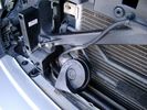
Wire (tubing) loom on right to down into bumper 462 viewsThis shows the 19mm loom in the trough between the bumper and the rad as it drops down into the right fog light area.
|
|
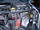
Wiring (tubing) loom at left headlight showing FASKIT panel 581 viewsThis shows the wiring (tubing) loom and FASKIT panel mounted to left wing. The loom moves a a couple of inches (50mm) towards the bottle once the headlight is put back in as there is not enough free space for the loom as located. The FASKIT panel is just visible at the top left corner of the picture.
|
|
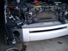
Wiring, (tubing), loom exiting temporarily from the front right fog light.565 viewsThe front axle air valve block is located just behind and below the fog light. Access to the valve block is by removing the right front fender liner, (or the bumper). The FASKIT lines are attached to the left and right front air spring lines at this location; also compressor air is taken from this location as well. Cutting the lines at as few different locations makes it easier to find leaks at a later date. As above, five 6mm air lines run from the FASKIT panel to the front axle air valve assembly and run within the loom. Two pair of the lines are for control of the air springs, and the fifth line taps the air supply at the valve block assembly off the compressor. This will be the air source line rather than tapping in directly to the high pressure air tank.
|
|
|
|
|