Power Window and Door Lock Circuits |
 |
| TITLE |
+ |
- |
| FILE NAME |
+ |
- |
| DATE |
+ |
- |
| POSITION |
+ |
- |
|
|

Alarm System description and Operation1039 viewsThis 9 page pdf explains in detail how the anti-thief, (alarm), system is supposed to operate. The system uses the door ajar switches to provide alarm system signals; as such there are few separate contacts related to the alarm system only.
Page 6 of 9 is of particular interest as it describes the trigger log that is accessible with the dealer T4.
|
|

Central Door Locking Operation Description1449 viewsThis 17 page pdf explains how the door locks are supposed to operate. Note that on page 9/17, the explanation of the operation of the hood ajar switch is wrong. It operates similar to the door and tailgate ajar switches; that is when a "door" is closed, the switch is closed to maintain a ground back to the CJB. Opening the hood, door, or tailgate removes the ground breaking the circuit and hence allows for an alarm condition.
|
|

LLumar AIR80 Air Blue 78 windscreen film IR reduction metal oxide339 viewsThis pdf summarizes the characteristics of the various types of window glass film available from LLumar. www.llumar.com
I had the Air 80 metal oxide sort of clear film, (windshield film they call it), installed on the front driver and passenger side windows to reduce the Infra Red penetration and hence heating effect on the front occupants. The film is barely visible from either inside or outside, however there is a noticeable reduction in heat penetration when sitting inside. In short, my arm does not get cooked.
Cell phone and GPS etc seem unaffected by the metal oxide film.
I also had the film installed on the three sun roof portions as well.
|
|

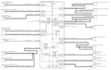
Power Window Circuit centered on Central Junction Box (behind glove box fuse panel)726 viewsRelay 143, the power window relay, and most other relays and FET's as well are built into the back of the passenger side behind the lower glove box fuse panel.
As such, the relays etc are not removable, jump-able, or serviceable.
|
|

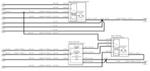
Power Window Circuit Sheet 2 Central Junction Box to Passenger Front Switch361 views
|
|

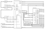
Power Window Circuit Sheet 3 Central Junction Box to Rear Switches387 views
|
|

Component Names related to Power Window Wiring Diagram279 views
|
|

Power Window Components469 views
|
|

Power Window Circuit Sheet 1 from Battery to Central Junction Box (fuse box behind glove box)346 views
|
|

Power Door Lock wiring diagrams523 viewsI thought I would include this 5 page power door lock wiring diagram pdf here as well.
When the pdf loads, if the views are vertical, it may be that you can right click on your mouse and a box will come up that will allow you to rotate the views clockwise so that the sheets are horizontal. Alternatively you can download the file and print each sheet yourself.
|
|

Power Window Wiring Diagrams407 viewsThis pdf shows the power window wiring diagrams which are also shown as jpgs 1,2 and 3 below.
|
|

Seats and Memory Description and Operation224 viewsThis 14 page pdf details the operation of the key fob memory functions related to the seats, and on page 7/14, the dip function re the exterior mirrors.
|
|
|
|