| Search results - "call" |

For all those SWMBOs - a place called SHOP101 views
|
|
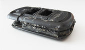
Tagliare lungo il perimetro della chiave - Cut along the key perimeter16 viewsI gusci sono saldati ad ultrasuoni. Con il disco tagliare lungo il perimetro della chiave in corrispondenza della giunta: lo spessore è di circa mm.3. Io non sono andato fino in fondo per evitare di danneggiare qualcosa, una volta inciso il solco per mm.2,7 ho fatto leva col cacciavite e ho strappato il materiale restante.
The body is ultrasonically welded. With the disc cut along the perimeter of the key in correspondence of the joint: the thickness is approximately 3mm. I have not gone all the way down
|
|

Embroidered T-shirt96 viewsEmbroidered in Khathmandu in a shop, from any design, by hand, overnight.
(9N1SC is a radio call-sign)
|
|
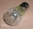
Land Rover Stop Tail Light dual filament bulb nominal 12 volt 21 / 5 watt filaments1412 viewsThis is the Land Rover part number 264590 dual filament bulb, (P21/5), that inserts into the upper two tail lamp receptacles. In the upper one, both filaments function, in the lower one, only the 5 watt tail light filament functions.
I regard it as not a good practice to routinely switch bulbs when the tail light filament, (5 watt), burns out on the lower bulb. The broken filament can jiggle over onto the brake light filament, (21 watt), and short the circuit to ground or something else not predicable.
There are also arguments to say that quality control is better on the Land Rover marketed bulbs than say far east sourced bulbs. Filament construction, and hence resistance can vary and mislead the current sensing circuits monitoring the signal light systems. Also when the bulbs are properly installed, all filaments should be standing vertically and not at any slope.
These are the sort of obscure circumstances that can lead to false trouble messages on the display, dropping to the stops, and subsequent concerns - all over a tail/signal light bulb.
For example, the filament life of both the tail light and the brake light filaments in the P21/5 bulb is significantly less than the USA common 1157 dual filament bulb, (1000/250 vs 5000/1200 hours); brightness in the P21/5 is a bit more, (3cp/35cp vs 3cp/32cp where cp is candle power), but current consumption is oddly less, (0.44a/1.86a vs 0.59a/2.10a where a is amps). It is the quest for efficiency vs maintenance trade off.
|
|
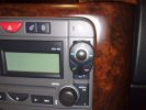
position of buttons for Parrot phone102 viewsthis can be put basically anywhere as it connect via bluetooth to the rest of the system. It is self powered (lithiam battery in it) so just stick it anywhere with no requirements for finding a live wire etc
|
|
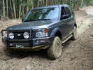
fun in the mud316 viewsCALENDAR ENTRY 2011
This is in Puerto Rico. The area is called \'cielito\' (little sky).
|
|

Rescue Call Out 392 viewsRescue Call Out in North Yorkshire; Cleveland Search and Rescue and the Police
|
|
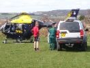
Rescue Call Out 86 views
|
|

Mount McCall 4wd track155 views
|
|
5mm Allen key showing the gap - can lift vertically to go flush111 views
|
|

Add A Circuit Littelfuse Data sheet2264 viewsThe switch connects to what Littelfuse brand calls an Add-A-Circuit model FMH200BP which is an adapter that plugs in place of a Mini fuse and then has space for two Mini fuses, (original and a second one). In this install, only the original 5 amp fuse was used - adapter was so as to route power from fuse box thru fuse, then rocker switch, and then back to fuse box.
Before you install the Add A Circuit for this application, take an ohm meter and trace out the circuit path of the four slots that fuses could insert into. The path is more complicated than one might first think. As such, the orientation of the fuse holder in the socket matters for this application - that is for a circuit diverter, rather than accessory adder.
|
|
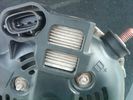
Alternator Plug and B+ terminal910 viewsPictured is the rear of the older Land Rover part # YLE500190 alternator showing the shiny cooling fin of the Regitar VRH2005-142 regulator under.
The first pin in the far left side of the connector is numbered #1 in the LR electrical wiring diagrams and is Battery Voltage Sensing (BVS); the middle pin, #2 receives a Pulse Width Modulated (PWM) signal from the Engine Control Module (ECM), and the right pin, #3 carries a PWM signal back to the ECM. Terminal Pin #2 on the LR wiring diagrams is called Alternator Control or ALT CON; Pin #3 per LR is called Alternator Monitoring or ALT MON.
Pin #1 is similar to what in older designs used to be called A or Batt, but is now called by Denso, S, AS, or Alternator Sensing for this design. Pin #1 also provides power to excite the alternator at startup until the PWM instructions over ride the battery voltage info. Land Rover calls the electronics under the pins a Smart Regulator, ironic, as it has to follow orders from the ECM rather than give the orders - new age thinking I guess. This is different from older design internal regulators that look at just the battery or the electrical buss voltage and then decides itself what to do.
It is almost like we are back to the external regulator designs of old, except that the ECM may decide that instead of telling the alternator to make more power, to load shed, and hence shut down the heated windscreen, seats, or whatever other electrical loads it decides are appropriate. My view is that the "smarts" are in the ECM and that the "regulator" should be regarded if not dumb, then as being a slave to the ECM.
|
|
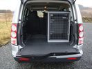
B24 TransK9 Dog Transit Box for Discovery 470 viewsThis box is designed specifically for the Discovery so that the 6th seat can also be used.
|
|
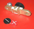
Battery Disconnect side post with + & - caps under view738 viewsThe upper and lower pieces of metal are clamped together but electrically seperate from each other. The connection between the two pieces is via the threaded part attached to the knob. When the knob is turned tight, current will flow between the two sections of metal.
|
|

193 views
|
|

166 views
|
|

120 views
|
|

130 views
|
|

156 views
|
|

94 views
|
|
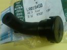
Breather Cap part # LR0194501509 viewsThis is the replacement breather cap as manufactured by the Gore Tex people, (Gore), for the engine compartment end of the front differential breather line.
You can with some difficulty, both blow and suck thru the breather filter material. The Gore Tex filter material has what are called hydrophobic and oleophobic properties. This means the filter material keeps oil in and water out, while at the same time, allowing air pressure to slowly equalize, (air permeable). Additionally, the transfer of dust, salt, and road debris is inhibited.
|
|

8 views
|
|
12 views
|
|

Thread upload14 viewsImage uploaded in thread 168929
|
|

Callistemon viminalis (Bottlebrush)125 viewsPhoto courtesy of Murray Fagg (an expert on Australian plants).
|
|

77 views
|
|

4 views
|
|
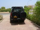
Rear end294 viewsLocally made wheel covers. LH is zipped from bottom to top to fit over registration plate with zip fasteners top and bottom. Rear IPF Reversing /camp lights on rack linked to reverse light circuit.
|
|

I think reverse gear is called for. Ooh my sump guard was still straight here!95 views
|
|
D2 in Fife 201114 viewsShe was called Fi
|
|
Recall work63 views
|
|

That's why they're called Ridgebacks343 views
|
|

v8157 viewsclose call this weekend
|
|
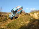
v8133 viewsClose call this weekend
|
|

Calliope Hummingbird (Stellula calliope)46 views
|
|

calendar entry 2009528 viewsHigh in the Iceland Interior June 2008 - F88 to Askjar Volcanoe - The mountain is called the "Queen of the Mountains - Herðubreið" Car is G4 Challenge Event Car from 2006 - Team Germany / Spain - Stage 3/4 Bolivia
|
|

Thread upload3 viewsImage uploaded in thread 174456
|
|

Exploded Parts view calling up 6R60/80 and 6HP26/28 variations3094 viewsThis single page jpg exploded parts view indicates some commonality between the Ford and ZF versions of the early and later six speed units. Technically this sheet is for the RWD units as there are variations between plain RWD units, 4WD, and AWD. The transmission in the LR3 is called by ZF to be a 6HP26X and by LR in some publications, the 6HP26
|
|
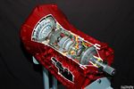
Ford 6R60 six speed cutaway showing torque converter.2188 viewsThis is a cutaway of the Ford 6R60 six speed which is a Ford license built version similar to our ZF 6HP26 six speed speced on early 3's.
The newer 3's and 4's have the ZF 6HP28. The Ford version is called the 6R80 and variations of it are used on the Raptor. As such, the Raptor metal pan can be installed on the 3's tranny but the deeper Ford Raptor pan does not have a drain plug.
|
|

137 views
|
|

47 viewsFuel Pump recall
|
|
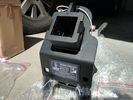
Rhino Tow Loop Hitch263 viewsThis is a receiver end view of the Rhino Hitch that ties to the factory tow loop. In addition to improved strength, it does not reduce ground clearance as does the factory style when installed.
Land Rover in early advertising videos when the 3 first came out showed the D3 hanging from a crane via the frame. The intent was to show how strong the frame is and by inference, the rear tow loop, specifically noted as being good for 6 tonne. The video ends before anything dropped or was lowered back to the ground, so one of course does not know for certain. The Rhino Hitch design however picks up on the apparent evidence of strength and certainly the additional clearance.
|
|
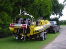
Now Thats What I Call A Rib46 viewsSpot the old P38 towing my baby. Sorry its an old photo.
|
|

Recall vacum pipes79 views
|
|

brake vacum pump recall41 views
|
|

Cyc.202 viewsOne of My dogs. Cyclops. Yes he has two eyes. He is called Cyclops because He used to walk backwards, sometimes, when he was a pup & He is a monster.
|
|
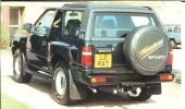
1994 Vauxhall Frontera, how they ever got away with calling it a \'Sport\'!119 views
|
|

Salisbury Plain299 viewsMy other club (Range Rover Register) had a plains day, ironically none of the 5 vehicles present were RR but 3 were at least from the same factory!
|
|

SUN-LR_SET195 viewsThis pic has been taken in Italy,it was almost dark,but the sun was still illuminating the bottom of this high altitude clouds called cirrus
a perfect atmospher
|
|

273 viewsThis pic has been taken in Italy,it was almost dark,but the sun was still illuminating the bottom of this high altitude clouds called cirrus
a perfect atmosphere
Piadina is the man!
|
|
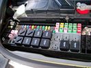
Picture of the engine compartment fuse panel5752 viewsEngine compartment fuse panel located near the battery. This is where F3E, (5 amp), F26E, (20 amp), Fuseable link 10E, (60 amp) and Relay 7E, the now upgraded 70 amp air compressor motor relay, part number YWB500220, (E is for Engine compartment fuse box), are all located. Fuse F35P, (5 amp), is inside the Passenger compartment behind the lower glove box door.
To keep the suspension from going down to the stops when driving, (or parked), it appears that it is only really necessary to remove F26E to depower the exhaust valve and generally keep all the valve block solenoid valves in a closed position trapping whatever air is within the air springs. F3E gets its power thru F26E, so when F26E is removed, the F3E circuit is automatically de-powered. F35P is more interesting in that battery power goes thru the ignition switch and F35P and then into the air suspension control unit. Apparently however, if F26E is removed, removing the F35P is not needed even when the engine is running.
With all fuses still in, if you have a problem, in practice, ideally, the compressor still works and will raise the 3 to an appropriate height. If so, one can then shut the engine off and allow the computers to go to sleep and then you remove the fuse(s). In actual practice, it seems that one need only pull the F26E fuse and can do so with the engine running. All the same, one might consider that the 3 is first a mobile computer, and secondly a 4x4. Computers prefer to go to sleep before the plug is pulled on them, however given that F26E circuit is always alive, then the computer never sleeps. With the fuse(s) pulled, and if you are still up, you can now be a 4x4 instead of a low rider. The whole purpose of the fuse pulling exercise is to depower the one and only system exhaust valve that is physically located within the compressor unit, (to keep it from opening), and secondarily to keep closed the four air spring solenoids within the block valves. This also shuts the air compressor down and stops the air compressor from making air even if the compressor is still good. That is why you initially need the fuse(s) in to allow the compressor to make air if it can.
|
|
The Pipes, The Pipes are calling456 views
|
|

Switch is blue colour thing thru the rectangular opening.3149 viewsThe blue coloured plastic bit thru the rectangular opening is the brake light switch. The fist time, I found it easier remove the switch by dropping the horizontal plastic panel, (two screws), and then slipping my hand in and rotating the switch clockwise 1/4 turn. The second time, I was able to remove the switch thru the rectangular opening and did not need to remove the horizontal lower panel. Obviously, I had to remove the sloping knee pad panel, (note sort of hinged at the bottom so pull back from the top.)
Regardless, do not touch the brake pedal - just let it sit where it wants to. One has to first remove the angled knee pad panel that sits under the steering wheel. It can be pulled from the top corner at the door side. Pulling releases a pair of those U shaped metal clips that LR loves so dearly. You have to pull quite hard. The bottom is held by a couple of plastic fingers in a couple of slots so you pull at the top till the two clips release and then rotate the panel and pull upwards a bit.
To remove the switch, you rotate it clockwise and pull outwards. Rotating the switch clockwise automatically retracts the plunger back into the switch body away from the brake pedal arm.
Similarly when you install the new switch, the required 1/4 turn anti clockwise rotation action releases the plunger so it lays up against the brake pedal arm and at the same time, secures the switch in place.
To remove the electrical wires, the switch will drop below the horizontal pad and hang from the wires so unclipping the electrical connector plug is fairly easy to do.
|
|
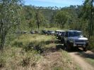
Start of easy hill climb169 viewsTR mode Rock Crawl - although I did turn off Hill Descent as the other side was not too steep and she wanted to keep slowing dramatically which I didn't appreciate in convoy. (Where is my old Pajero that had the inclinometer?)
|
|

Chief instructor (left) and another instructor explaining water crossings200 viewsWhilst no one tested the waters this time (they did last week with another group) you can just see the stick floating in the water (near second instructor's right elbow). Satisfied that the rains hadn't changed the depth dramatically, they let us through - those that elected to take the water crossing of course.
|
|

child cage68 viewsdont call the NSPPC just yet just to show how a 2yr look in the cage
|
|

7 viewsXmas Presy from my so called work mates!
|
|
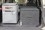
54 viewsengel fridge and cargo drawer rear of the D3.
Base board is MDF, think this may be called ply elsewhere covered with marin carpet on both sides and screwed through the 4x tie down holes with M10 bolts
|
|
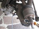
dont know how to call it removal (omocinetico)68 views
|
|
dont know how to call it (omocinetico calettato)76 views
|
|
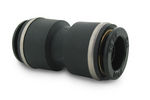
John Guest DOT all plastic fitting714 viewsThis is a picture of the John Guest DOT all plastic union. If you look closely, you can see the DOT imprinted in raised letters on the end of the fitting. This is of a 1/4" connector rather than the 6mm that the 3 requires.
The picture is similar to the air suspension pneumatic fitting union that Land Rover sells as replacement part # STC8580. This is for 6mm OD tubing size. The STC8580 comes with what are called "Collets" at each end that cover up the press to release feature underneath. See the John Guest web site www.johnguest.com under the Pneumatics section and also in Downloads for their catalog for install and remove instructions.
The actual "air brake spec" fitting that Land Rover provides has an interior 4mm OD ferrule that slips inside the 4mm ID of the nominal 6mm tubing. I have not yet been able to obtain the John Guest part number for the LR fitting, only the LR part number. This part number was generated for the RR Classic air systems.
|
|

John Guest (LR part # STC8580) push in straight 6mm tubing to tubing connector727 viewsThis picture is similar to the air suspension pneumatic fitting union that Land Rover sells as replacement part # STC8580. This is a 6mm OD tubing size push in to install straight tubing to tubing fitting. The STC8580 comes with what are called "Collets" at each end that cover up the press to release feature underneath. See the John Guest web site www.johnguest.com under the Pneumatics section and also in Downloads for their catalog for install and remove instructions.
The actual fitting that Land Rover provides has an interior 4mm OD ferrule that slips inside the 4mm ID of the nominal 6mm tubing. Hence the fitting depicted and part number are not actually correct. I have not yet been able to obtain the John Guest part number for the LR fitting.
The fittings that show in this doc are what I call food service fittings rather than transportation or Air Brake fittings. The part LR sells, (STC8580), is the Air Brake type for transportation.
|
|
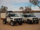
Lake Coongey. The project vechle and Micheals mighty D3142 viewsStoped for lunch and to do some boating with the inflateable boat, kids paddled to the other side and after trying to call them back D2 was dispatched to the other side to bring them bach but by thr time D2 got to the other side they had paddled back, we thought if was funney but the D2 driver definitly did not, ha ha ha!
|
|

Thread upload5 viewsImage uploaded in thread 184153
|
|
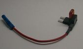
Littelfuse Mini Add-A-Circuit FMH200BP and OFH0200ZP1610 viewsFound this jpg somewhere on the forum - others are using them as it is a good way to tap the fuse box to add a fused circuit, or in this case, to modify a circuit to add a switch such that the fused circuit is switched. In my SmoothTalker gallery, there is a PDF from Littelfuse specifically related to this Add-A-Circuit device.
Before you install the Add A Circuit for any application, take an ohm meter and trace out the circuit path of the two pair of slots that fuses could insert into. The path is more complicated than one might first think. As such, the orientation of the fuse holder in the socket may matter depending upon the application. If the application is a circuit diverter, (as the F35 mode is), as opposed to a mere accessory adder, orientation matters.
|
|

LLumar "windscreen" clear Infra Red reduction side window film920 viewsThis is a data sheet on the LLumar brand of what they call Windscreen Film; It is almost clear, (has a bit of a blue tint), and reduces both the Ultra Violet fading and sun burn rays which most all films do as that is easy, plus more significantly, the Infra Red heat rays. That is rare as it is not so easy or cheap to do.
AIR80BLSRHPR (blue) is what the IR rejection film is listed as in the brochure that I used. http://www.llumar.com/en/AutoWindscreen.aspx
I had it applied to the front side windows as well as the front sun roof. One can feel the difference when the sun is low and streaming thru the side glass or high and coming thru the sun roof. Rolling a side window down is the simplest test of effectiveness re the rejection of the heat energy.
|
|

LLumar AIR80 Air Blue 78 windscreen film IR reduction metal oxide339 viewsThis pdf summarizes the characteristics of the various types of window glass film available from LLumar. www.llumar.com
I had the Air 80 metal oxide sort of clear film, (windshield film they call it), installed on the front driver and passenger side windows to reduce the Infra Red penetration and hence heating effect on the front occupants. The film is barely visible from either inside or outside, however there is a noticeable reduction in heat penetration when sitting inside. In short, my arm does not get cooked.
Cell phone and GPS etc seem unaffected by the metal oxide film.
I also had the film installed on the three sun roof portions as well.
|
|
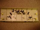
Boot lighting panel, wiring side up 279 viewsThis shows the back side of the plastic cover panel on which the two LED lights are mounted.
Also of note is the SPST rocker switch to switch the new lights off independent of the the Land Rover W5W light.
The new light pair will only power up if the Land Rover light is powered and hence dims and automatically goes off along with the Land Rover light.
The Black wire is ground, the Purple wire is +12VDC.
|
|
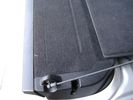
Flexible wire rope fishing leader 0.032" diameter exiting carpet 1931 viewsThis is all you see of the completed mod.
The short little angled "line" about an inch long that looks like a piece of debris and is located a few inches "above" the support cable is actually the wire rope release cable exiting from under the carpeted lift gate cover.
I drilled a very small hole in the carpet and pushed the 0.032" diameter release wire thru and then slipped the loose end under the black plastic.
To release with the lift gate etc closed, from the inside, just pull the loose end free from under the black plastic and gently pull wire about 5mm, (1/4"), and the upper door catch should release. You will have to manually push the upper door out wards to actually effect opening, but you will already be inside the rear cargo area so that part is easy to do.
The assumption is that the lower door latch still works electrically and hence, the lower lift gate half will open as normal by pressing the usual button on the top left of the lower door half.
|
|
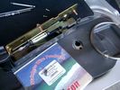
0.032" OD metal fishing leader and lead fishing weight clamped to existing wire rope 2104 viewsI used a size #0 lead fishing weight as a clamp to attach the 0.032" diameter flexible wire rope fishing leader to the release cable.
The pictured weight is the smaller #00 weight, however it did not work very well so reinstalled with the larger #0 size. I clamped to the cable as what breaks is the L retainer that is hidden in the actuator and holds the cable. When the L breaks, it lets go of the cable so you hear the clicking but there is no opening action.
Clamping on to the cable is an attempt to resolve that reality; also if the actuator electrically fails, the release mod should still do the task. Note in the picture the two Torx T15 screws that hold the gold plate to the plastic case and also the two 8mm cap screws that have to be loosened to remove the actuator from inside the door.
|
|
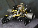
Rear Differential cutaway with E-Locker 1199 viewsThis jpg is from the link below.
There are another ten or so cutaways plus a whole file group showing a 2005 LR3 sectioned for the 2005 Chicago Auto show. Each jpg has an enlarge function to the bottom right of a main picture.
On one jpg you can see right into the stepper motor.
http://www.cutawaycreations.com/cutaways.php?project=land-rover-electronic-rear-differential#/IMAGES/car4/images/image1.jpg
Both the front and rear differentials are manufactured by Dana Spicer in the UK. Dana calls them a Clamshell design.
|
|
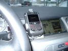
Blackberry Tour mounted on air vent showing default analogue clock 211 viewsA characteristic of the Blackberry is that when charging, the display can default to an analogue clock. Hence when the unit sits in the holder, the phone is being charged and the analogue clock displays. When the phone rings, the clock disappears and the call id displays.
|
|
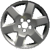
LR3 Sparkle Silver 6 spoke Wheel Cromodora of Italy 19 inch x 8 ALY72191U1106 viewsThese are the standard equipment 19" wheels on the 2005 LR3 HSE. The wheels are Made in Italy by the Cromodora company. Each are rated at 940 kg (2,072 pounds) and have an offset of 53 mm positive, (53P or +53).
I mention the 940 kg load rating as that is about the heaviest rating of any Land Rover product. The RRS and RRHSE both have lower ratings. What this means is that while a wheel from a Range Rover may physically fit, it probably does not have the brute strength of the factory spec Land Rover 3 wheel. There is no Land Rover product heavier than the 3, hence the 3 wheel design spec is the heaviest of the bunch.
|
|
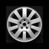
LR3 Sparkle Silver 10 spoke Wheel Cromodora of Italy 18 inch x 8 ALY72190U725 viewsThese wheels are factory standard on the 2005 LR3 SE and Made in Italy by the Cromodora company. Each wheel is rated at 940 kg (2,072 pounds) and has an offset of 53 mm positive, (53P or +53).
I mention the 940 kg load rating as that is about the heaviest rating of any Land Rover product. The RRS and RRHSE both have lower ratings. What this means is that while a wheel from a Range Rover may physically fit, it probably does not have the brute strength of the factory spec Land Rover 3 wheel. There is no Land Rover product heavier than the 3, hence the 3 wheel design spec is the heaviest of the bunch.
|
|

Wheel cut thru definitions and specs894 viewsNote the location of REAR SPACING and also OFFSET; probably two of the most important dimensions and not always understood as related to wheel size and relationship to the brake components.
For the 3, Rear Spacing is approximately 6.5 inches or 165 mm for a nominal 8" rim. Offset is 53P or 53mm Positive, which means the distance from the machined hub flat mounting surface to the rim's true centreline is 53 mm in the outboard direction. (The rim illustrated has a negative offset.)
As Positive offset increases, this means the wheel wraps around the disc brake mechanism more deeply, and hence the more the wheel would cover the brake parts. This is why most 18" wheels will not fit with the larger Brembo "supercharged engine" brake calipers.
Pitch circle diameter is 120mm; Pattern is 5 lug, and the tyre load rating is 112 with a recommended tyre speed rating of H or higher along with the XL load rating. For the 3, the stock tyre diameter is about 30 inches. The 255/60/18 or 255/55/19 OEM tyre outside diameter is 30.04 inches; Wheel lug torque is from 130 to 150 Nm or 96 to 110 lbf-ft and the lug nut hex socket size is 22mm.
Max Load High Speed Driving Tyre pressures are Front, 33 psig, (230 Kpa) and Rear, 42 psig, (290 Kpa).
The OEM rims are rated at 940 kgs, the highest that LR makes, hence while rims from other Land Rover products may physically fit, the odds are they are under rated in a weight sense.
|
|

Underhood Fuse and Relay Box drawing 3041 viewsShows the various fuse and relay locations. Fuse 3E, (5 amp), and Fuse 26E, (20 amp), as well as upgraded 70 amp Relay 7, part number YWB500220, locations are displayed. Relay 7 sends battery power to the compressor from the 60 amp fusible link called up as 10E. Fuse 26E is what provides full time always on battery power to the air suspension ECU and hence powers the auto level wakeup when the vehicle is shut down and say parked for the night. Removing F26E is the primary method to disable the air suspension system; Removing F35P is more if you want to experiment with it from inside.
I found it useful when I had a suspension problem, (actually a wheel alignment problem picked up by the steering wheel angle sensor), that only showed itself on the highway but allowed for no trouble light driving in the city. This was because in the city, the steering wheel was always in motion and rarely was the vehicle driven in a near straight line for very much distance.
|
|

LR3 Denso Alternator YLE500390 pulley view817 viewsNote the DENSO sticker on the side. Denso calls their nominal 150 amp 12 Volt alternator an SC2 design. SC means Segment Conductor which apparently increase the winding density of the stator coil, hence yielding a physically smaller lighter alternator for a given output. I presume the 2 means the second try at getting it right. A Denso part number is 4280003690 for the alternator, (there are others, as below).
Rotation is clockwise and the 54mm diameter pulley has 6 grooves (PV6x54). Count the pulley grooves on both the one you remove and your new one - some replacement alternators seem to ship with 5 or 7 grooves so you might be swapping pulleys.
A previous LR part number was YLE500190 for the older variation of the newer YLE500390 unit.
An additional part number for a factory rebuilt is Nippon Denso 210-0569 for the petrol V8 alternator. Other Nippon Denso numbers include 104210-3690 and 104210-3691. The Lester number is 11206 which relates to another Denso number of 290-5287. WAI uses 11206N.
From 2006 to 2009, the internal regulator is a Transpo IN6349 and of the B circuit type if it can be said that applies to PWM, (Pulse Width Modulated), regulators.
The "regulator" inside the alternator is therefore really not a regulator in the old sense of the term but instead an instruction receiver from the ECM that translates Pulse Width Modulated (PWM) signals into a form that the alternator understands – digital like signals from the Engine Control Module(ECM) into analogue like signals that the windings understand.
|
|

LR3 Denso Alternator YLE500390 rear view705 viewsThis picture shows the rear of the YLE500390, the Land Rover part number for a newer design alternator utilizing the Transpo IN6349 regulator with the "hidden" cooling fins. Note the visual difference in the rear view of the next file jpg.
If the alternator is a rebuilt, (service exchange unit), but Land Rover supplied, then the part number is LR008860 or similar. (Note that 0 in LR0 is zero.)
Two Denso part numbers exist for the alternator as well, 4280003690 and 4280003691. The rating of the petrol V8 alternator is nominal 12 VDC and 150 amps. In normal day to day operation, they seem to run about 14VDC - usually between 13.9 and 14.1 volts at the OBD port.
For the petrol V6, the LR service exchange number is LR008862, and the 2.7TDV6 is LR008861.
The bridge rectifier within the alternator is a 12 diode avalanche type, 117mm diameter, as used in Nippondenso 120 to 160 amp alternators with the Hair Pin stator. It is similar to a Transpo INR421 which is rated for 120 to 150 amp alternators. That is probably our primary problem - the rectifier is just too light. Alternate part numbers for the bridge rectifier are Cargo 237607, Mobiltron RM-29 and AS ARC6021.
Re the B+ stud, the INR421 calls it up as an M8 x 1.25 x 30 mm long course threaded stud; some say 34 mm but that may be longer than desirable.
|
|
![Filename=LR3_BMW_Ford_ZF_6HP26X-28X_Catalog_with_metal_pans_[1].pdf
Filesize=1194KB
Dimensions=320x240
Date added=26.May 2011 LR3_BMW_Ford_ZF_6HP26X-28X_Catalog_with_metal_pans_[1].pdf](images/thumb_pdf.jpg)
ZF 6HP26X and 6HP28X transmission parts showing various pans2799 viewsThis 42 page pdf is probably the most informative of all the material in this album. It is called a spare parts catalog but is much more than that. The material is specifically for the X variety of ZF six speed transmissions that are in the Land Rover 4WD / AWD models as well as BMW and Ford AWD vehicles.
|
|

Door Lock Wiring Diagrams1717 viewsNear the bottom of this 5 page pdf on page 224 are shown the pushbuttons and locking mechanisms for the rear hatch and tail gate.
The pdf will open vertically but you can download and print it out or just rotate the image clockwise by right clicking on your screen and selecting the "Rotate Clockwise" button.
|
|

Horn Wiring Circuit LR3575 viewsThe is the wiring diagram for the dual horn circuit.
The Horn Relay, (R133), is not a big black thing hidden somewhere but instead what is called a FET, (and it is hidden)!
This is a Field Effect Transistor that is built into the circuit board that is mounted to the back of the fuse box that is located behind the lower glove box door on the passenger side of the 3. The related 15 amp fuse, 12P, is mounted in this fuse box and is often called F12P, where F is for fuse, and P is for Passenger compartment.
This is to help differentiate from another fuse and relay box, (the usual kind), that is located beside the starting battery in the Engine compartment. FxxE is often used in the naming of those fuses.
|
|
![Filename=LR3_Radio_Removal[1].pdf
Filesize=190KB
Dimensions=320x240
Date added=04.Feb 2014 LR3_Radio_Removal[1].pdf](images/thumb_pdf.jpg)
Radio Removal from Radio Stack567 viewsThis shows how to remove the radio from the stack. Basically you remove the H surround first and then at least loosen all the Torx 20 screws left and right sides from the top down starting at the narrow unit that the four way flasher/locking buttons are mounted on.
The units kind of interlock, hence some movement of each is required to remove the radio by itself. I find it best to take out the four way flasher/locking buttons assembly first as that allows access to the fibre optic cable connector into the back of the radio head without too much tugging.
|
|

Stop Light Lamp Circuit pdf2460 viewsThis pdf shows the brake light circuit for the NAS LR3.
Note that power for the brake light bulbs can come either thru the brake light switch power feed /contacts plus also from the Hill Decent Control, (HDC), system relay located within the Central Junction Box, (CJB) - yes two separate sources of power for the brake light bulbs. This would tend to explain how a brake light circuit concern shows up as a hill decent fault message; also why lesser vehicles without hill decent braking mechanisms, (HDC), never display this sort problem when a brake light bulb or switch acts up. You never have a problem related to a system that does not exist.
Additional evidence of the relationship of the HDC and the tail light circuit is demonstrated by when the HDC actually acts to slow the 3 down, the brake lights automatically illuminate even if the slowing action was merely retarding the engine speed or shifting to a lower gear, (in other words, no foot on the brake pedal).
There is also a tie in to the Cruise Control and hence a failing brake light switch can affect cruise operation or just create false Cruise Control messages. To further complicate the issue, while there are no messages generated, operation of the radiator electro viscous fan can also be negatively affected by the fouled set of secondary contacts within the brake light switch. This is all because the NC contacts within the brake switch send misleading messages to the ECU.
While the ground wire design is similar to other vehicles, note the grounds for the brake light filament and the reverse light filament are common on each side. That means that if one has a non functioning brake light on one side, the reverse light may not also work or that some problem with the reverse lights could back feed into the brake lights. This situation while unusual, can result when grounds are corroded probably due to swimming in rivers and creeks or just routine driving in a marine environment.
|
|

ZF 6HP26 Land Rover Transmission specs1667 viewsThis is just two sheets of paper with various numbers related to the 6HP26 such as oil capacity, gear ratios, and torque wrench settings for the fill and drain plugs.
You may note that LR calls this ZF transmission the 6HP26 whereas ZF calls out the LR3 transmission as the 6HP26X. Just what the differences are, I am not certain however the X refers to 4WD or AWD use as opposed to solely 2WD.
Zahnradfabrik is what ZF is short for and translated from German, roughly means Gear Factory.
|
|

Magcode power port90 viewsmagnetically held together, low profile internally and externally.
|
|
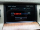
separate vol control for direction voice29 viewsthere are many voice options one of which is a chinese donald duck ..no really thats what its called
|
|

New bonnet decall183 views
|
|

P013-Russia Only - Recall Campaign announce66 views
|
|
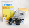
Philips D2S 85122 C1 Xenon 4300K projector HID bulb957 viewsThis is the 4300K OEM bulb in our HID Xenon projector headlights. People who design illumination systems regard the 4300K colour as a good compromise to provide what is called definition. This is effectively the ability to actually determine what an object being illuminated probably is. The more blue colour bulbs, say 5000K and greater, result in a reduction in the ability to distinguish detail, (regardless of brightness), of the object being illuminated. Effectively, you can see the object but you cannot quite figure out what it is. This is because the more blue frequencies means there are fewer other frequencies of light that allow our eyes to actually discern what an object really is.
The 4300K colour temperature applies to clear air conditions; for rain, dust, snow, fog, etc, then a yellow 2500K colour temperature is preferable. 2500K provides more contrast and there is less back splash of light off the air particles. In blowing snow, this means less sparkle back. Flat top cut off of the light beam, (which is the pattern our projector lights have), is important to reducing back splash - hence you do do not want roof mounted lighting for adverse conditions - as low down as possible is preferable, (which is why fog lights generally sit low.)
|
|

now thats what I call a bit of a bump443 views
|
|

Powerchip Australia - TDV6 Gold Upgrade199 viewsFrom an Aussie company that has advertised in motoring magazines for the last 8-10 years that I can recall. The cost is $AUD1491 (~596GBP). Does anyone know anything about them?
Booklet shows engine chart comparing standard with Powerchip's Gold 'chip'.
|
|

Brake servo recall work - new pipework118 viewsThis is the new visible result of the recall work just done
|
|

Thread upload24 viewsImage uploaded in thread 52311
|
|

Thread upload3 viewsImage uploaded in thread 175107
|
|

Transpo pdf explaining the operation of Ford PWM regulators616 viewsThe 4 page pdf produced by WAI-Transpo explains the operation of the Pulse Width Modulated regulators located within the alternators on our 3's. Of note, the pdf states that certain of the Ford PWM regulators do not meet Ford spec.
The pdf explains the function of all the terminals and the apparent advantages of the PWM style over previous designs. Note that Ford calls their "engine computer" a PCM, (Power Control Module), whereas Land Rover, an ECM, (Engine Control Module).
|
|

Rosen Owners Manual879 viewsThis 28 page Owners Manual is the Rosen version written specifically for the A10 model DVD Video Game Entertainment System player that may in attached to the roof of your 3.
Discussed is how to use the remote control, the wireless headphones, the TV feature if installed, and how to change from 16:9 widescreen format back to the older 4:3 format.
|
|

At the beach462 viewsInstalled the rails to bring home the Christmas tree. Installed them myself & quite proud of that fact since I\'m not the mechanically inclined type hehe.
|
|
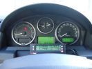
ScanGauge II on steering column of LR3797 viewsMAP is Manifold Absolute Pressure, what I call Vacuum.
The volts is I think the battery charging voltage as it moves around from about 12.4 when shut down to 13.5 when the batteries seems charged; 14.9 is about as high as I have seen it display.
You also have RPM, speed in MPH or KPH, coolant temperature and a bunch of other readings including sort of instantaneous fuel in a variety of units.
Also under some conditions, the ScanGauge will reset the MIL light as well. The background colour of the display can be changed to many different colours. I have it set to match the LR green.
|
|

Fold2 310 views
|
|
Thread upload22 viewsImage uploaded in thread 169412
|
|
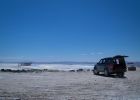
183 viewsMy dog didn't like the salt, smell, heat, glare, etc. He's a mountain dog. He basically plopped down in the shade of the D3 and waited for us to come to our senses and leave.
|
|
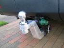
LR "plough" with 150mm high-rise alloy tongue.169 viewsI fitted this 150mm high-rise tongue to the LR towing hitch. It's a solid aluminium alloy unit called a "Stinger" or "Alumnistinger". Made in the US and available in Australia through a distributor in Brisbane Qld.
|
|
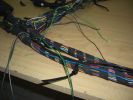
Wire swapping88 viewsPulling out the old cut wires while routing in the new, you can see some already done in the lower loom body. The loom will be re wrapped at the end so i only need to hold it in place periodically at this point.
|
|

Tekonsha P3 Brake Controller 90195 to Ford 3035-P wiring adapter plug306 viewsThis two page pdf is the general instruction for hooking up the Tekonsha part number 3035-P adapter cable between a Tekonsha P3 controller and the existing Land Rover/Ford plug, (called C2590 in the Land Rover wiring diagrams), that is hidden above the brake pedal.
The "Ford" plug, (C2590), is grey and is stuffed up above the brake pedal arm.
Mount the P3 controller appropriately and then connect one end of the custom cable to the P3 and the other to the "hidden" plug.
You will now have power for your trailer electric brakes in the round socket at the rear of your LR3; also no computer update from the Land Rover T4 unit is required. For once, it is plug and play.
If however, your trailer has LED tail lights, you may have trouble with the flashing of the trailer signal lights or non recognition by the 3 that a trailer is connected. As such, the little green trailer signal will not illuminate when a trailer is connected and the signal lights are used. This can affect the shifting of the transmission and much to your annoyance, the backup sensors will still be functioning rather than being auto disabled.
|
|
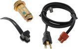
Block Heater and Cord for petrol V8 LR3 North America 120VAC523 viewsThe recommended 120VAC block heater cord is a Temro 3600003. This is a five foot long cord with what is called a Straight connector at the block heater end with holes for two pins; there is also a metal tab located between the two holes serving as the ground conductor. That cord, in addition to having the two pin holes plus ground tab end, is designed for both aluminum and brass heaters as that also matters.
The Land Rover part number for the Block Heater assembly is VUB504640 but is a Temro product not officially marketed by Temro as a Land Rover block heater. The Temro product number is 3100107 which shows as a brass body 30 mm threaded 700 watt 120VAC screw in block heater with a rectangular shaped depression and two pins suitable for the Temro 3600003 cord. Note the word BRASS as it mates with the aluminum OK.
|
|
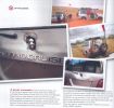
Snatch Strap Dangers207 viewsThis is from Overlander magazine in Australia. This very graphically highlights the dangers of using a snatch strap without adequate knowledge and training.
|
|

3 views
|
|

Termite mound 9 viewsNow that's what you call a Termite mound
|
|

vib recall210 views
|
|

TG Politically Correct Meeting159 views
|
|
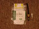
Voss System 203 connector 6 mm for valve blocks 900 viewsThis is Land Rover part number RQC000030, the Voss fitting for the axle valve blocks. I think it is a Voss System 203 6mm fitting, Voss part number 5 2 03 11 01 00.
The parts bag comes with the white plug inserted in the brass threaded bit with what is called the brass cutting ring placed on the tip of the white plastic plug. The idea is that one screws, (M10 x 1 thread), the brass insert into the appropriate hole with the white plug still in the brass insert. Once the brass is tight, (12 mm wrench), then the white plug is pulled from the assembly leaving the cutting ring down inside and under. One then pushes in the 6 mm tube end about 20 mm or so and the tube slides down thru the brass cutting ring, (2 internal sloped one way cutting ridges). When the tube is in far enough, one pulls upwards a bit and the ring cuts into the plastic such that the tube will not pull out. To remove tube, one unscrews the brass nut and all comes out, sort of like I have shown with the short piece of 6mm tubing. The white plug is a throwaway item upon install of the tubing.
|
|

Voss B203 Fitting Install954 viewsNote on the first page, the reference to DIN 73378 and D74324 and also PA11 and PA12 material when referencing suitable spec nylon (polyamide) air line for motor vehicles. I think some of the 6mm fittings used on the 3 for the valve blocks are the System 203 type and called up as Land Rover part number RQC 000030. The Voss part number is I believe 5 2 03 11 01 00.
|
|

Manufacturers brochure re plastic pan1027 viewsI found this ad from a German manufacture called LANXESS Deutschland GmbH saying that they manufacture the plastic oil pan/filter combo for ZF that is used on the 6HP26 six speed transmission.
|
|

ZF LifeguardFluid6 transmission oil.1386 viewsThis is an interesting pdf in that under the ZF 6HP26 six speed section, it provides the various automobile manufacturer part numbers for their version of the appropriate tranny oil, all of which seems to be the LifeguardFluid6 oil, ZF part number S671 090 255. Note the fine print and do not confuse it with the LifeguardFluid6 Plus oil for vehicles with the Torsen AWD setup such as the Audi Quattro, VW 4Motion vehicles and I think the BMW FF Range Rovers of an earlier time.
Also of interest at the bottom of the pdf is the recommendation for replacing the transmission oil "between 80,000 km and 120,000 km or 8 years, depending on the load." I also do not see any reference to "sealed for life" but almost as optimistic, "maintenance free" but with the proviso "intended for normal operating conditions". This would most typically be the Sandringham Castle Grounds in the UK rather than Cape York, QLD.
|
|
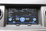
MP3 player to play music on the car system126 viewsUsing an app called mortplayer on the PDA to play mp3 files on the car's ICE system.
It has a nice interface meant for in-car use
|
|
|
|
|