| Search results - "hose" |

For all those SWMBOs - a place called SHOP101 views
|
|
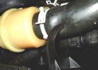
Hose displaced from support bracket315 views
|
|
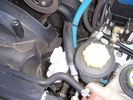
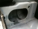
200 viewsRemoval of Intercooler hose, don't forget to plug the hole, don't want anything to fall in there
|
|

_DSC0188172 viewsThose Cows again!
|
|
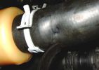
Damage to hose from tip of support bracket248 views
|
|
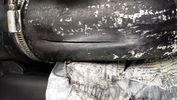
Thread upload131 viewsSplit after removing duck tape. I think the split got longer whilst waiting for new silicone hose's to arrive.
|
|
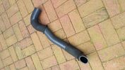
Thread upload125 viewsNew silicone hose with original sleeves refitted.
|
|
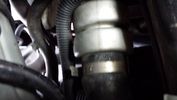
Thread upload128 viewsOriginal LR rubber hose just before removing (turbo end).
|
|
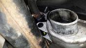
Thread upload122 viewsBottom end Passenger side after original LR hose removed
|
|
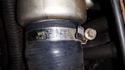
32 viewsNearside hose replaced with silicone type
|
|
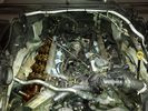
4.4 L Petrol Engine210 viewsIntake removed on V8 4.4L Petrol Engine to remove hose with T in it.
plse like my facebook page https://www.facebook.com/DifferentialPartsUS
|
|
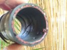
Split little intercooler hose 392 views
|
|
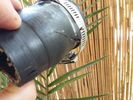
Split little intercooler hose 2105 views
|
|
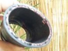
Split little intercooler hose 171 views
|
|
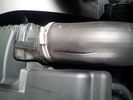
Intercooler hose crack10 views
|
|

new silicone intercooler hose vs old one7 views
|
|
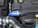
intercooler hose upgrade job done6 views
|
|
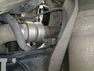
Charge Air Inlet hose - front mounting bkt86 views
|
|
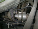
Charge Air Inlet hose67 views
|
|
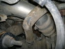
Charge Air Pipe - turbo end.101 viewsThe maint manual identifies releasing the pipe hose clip in the center of the photo. Pity who ever built this engine Put the hose in such a position that access to it was near impossible. I released the other clip at the turbo end of the flexi hose. Easy to get to but a right git to release the hose of the turbo.
|
|

Air con pipe65 viewsIts the brown pipe in the center of the photo. To remove this first you need to remove the "charge air cooler inlet hose" to allow access to the air con pipe securing fixings. But with the "charge air cooler inlet hose" disconnected it can\'t be removed from the veh because the air con pipe is in the way???
|
|
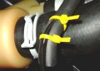
Repair to prevent hose damage245 views
|
|

Headlight washer hose84 views
|
|

LRO Show 2004 - Testing my 3 Month old Disco Metropolis - Those were the days!18 views
|
|
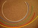
6mm Heat Shrink colours 362 viewsI decided to colour code the tubing so I used 6mm electrical heat shrink.
As there is no apparent colour coding re the 3, I tried to emulate the P38 coding; #1 LR red, #2 RR blue, #3 LF yellow, and #4 RF green. This was not doable as both left side air springs have green coloured tubing coming off the top of the front and rear air springs. I therefore arbitrarily chose the Left Rear to be red; Left Front green; Right Front yellow; Right Rear blue; and for the air compressor supply line, White coloured heat shrink. Since two new lines tie into each air spring line, I made the line between the air spring and the FASKIT, a single solid colour, and the line from the FASKIT to the valve block, White, plus the related appropriate solid colour.
|
|

Fin cell phone aerial drawing190 viewsThe factory aerial for the factory NAV / GPS on my 2005 HSE is within the high mounted stop light lens at the top of the upper hatch door. I do not have the factory installed phone kit, and as such, do not have the fin installed; instead there is just a plastic blanking insert to fill the cell phone aerial wiring hole in the metal portion of the roof; hence this requirement for an "external" cell antenna. For those that do have the fin on their glass roof, the fin is screwed on to a glued on plastic gasket, (sort of), and not bolted thru as per the metal roof 3's.
|
|
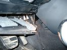
Air Conditioner Drain Hose on Drivers Side (LHD)2256 viewsThe corrugated rubber bit above and to the right of the gas pedal is the drain hose that goes down thru the carpet and floor sheet metal.
While it is bit hard to figure out from the jpg above, there is a rubber "strap" attached to the top of the corrugated hose that one uses to pull on to drag the hose up back around the black plastic heater "pan" drain. The same drain hose arrangement is on the other side as well.
One could I suppose run a plastic snap tie around the vertical pull strap if one was concerned about the hose slipping off again. See also the other jpg sketch which is from the Land Rover manual.
|
|
Thread upload9 viewsImage uploaded in thread 176039
|
|
Thread upload6 viewsImage uploaded in thread 176039
|
|
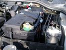
Aux Battery showing ground cable bolt "upside" down 1568 viewsIn order to obtain sufficient height clearance to get the plastic cover back on, I had to install the ground cable to the underside of the battery post connector.
Note the battery vent hose, (approx 5 ft required) is run down into where the windshield washer fluid container is located. There is not much electrical or metal in that area to be corroded by battery gas plus the open end of the vent hose tends to be protected from dirt and stays clean as well.
|
|
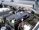
BCI Group 40R Deka 640RMF battery showing vent hose run forward to windshield washer reservoir area 1424 viewsRecessed post "Euro profile" battery to "match" OEM and stock Land Rover bracket; note that the Traxide SC80-LR module is mounted at an angle to allow for the main cable to sit under the cover so cover still closes.
The battery is a nominal 7", (180mm), high, but sits on a 1" battery spacer set under to raise the bottom front end of the battery such that the approx 11", (290 mm), length of the BCI 40R battery rises above the angled plastic nibs at the forward end bottom of the case front; hence sufficient space, (1/4", 5mm) remains at the brake reservoir end.
Also the 40R battery does not have hold down "flanges" on each end; on the sides yes, but not the ends so no additional length is required.
When I had to replace the 40R, this time I installed the shorter, (9.625"), taller, (7.5") Interstate BCI 47 / DIN H5 battery which eliminated the spacer on the bottom and better fit the stock LR tie down bolt lengths. Deka also has a BCI 47 / DIN H5 that would work fine as well.
|
|
Thread upload10 viewsImage uploaded in new thread
|
|

Coolant hose between water circulating pump and FBH45 views
|
|
145 views
|
|
Breather line with factory cap cut off.2275 viewsIf you expand the jpg by clicking on it, in the bottom right corner if you look closely, one can see the black plastic factory vent tubing with the OEM cap cut off.
Note the tubing is cut at a 45 degree angle facing to the rear. Also shown in the top right is the cut off portion sitting on the coolant water hose and on the top left also sitting on the coolant hose, the new to be installed Gore manufactured replacement breather cap.
|
|
Vertical Breather Hose before cutting off OEM cap.1740 viewsThis shows the plastic vertical breather tubing and OEM cap prior to being cut off. The tubing is located on the driver side at the front near the radiator. One cuts about 3/4" to 1" off from the top. The TSB says 20mm.
I tried blowing thru the cut off piece and was not very successful. The cap seemed plugged. I am beginning to think that there was a very good reason for Land Rovers's Technical Service Bulletin, (TSB).
|
|

Thread upload5 viewsImage uploaded in new thread
|
|

Alfa GT84 viewsFor those days when SWMBO takes the D3...
|
|
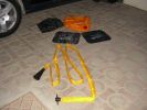
The kit as supplied180 viewsContains carry bag, 2 protector mats, exhaust jack and 7m reinfoced woven hose with bayonet connector to bag (inc non-return valve) and rubber cone for exhaust fitting
|
|
30 views
|
|
Thread upload25 viewsImage uploaded in thread 113360
|
|

Cooling system hoses - 4.4L petrol V81098 viewsThese are the cooling system hoses on the 4.4L petrol V8. The little odd shaped bleeder hose, (LR006158), shown in the top right hand corner can give problems. There is a plastic tee with a threaded air bleeder outlet located in the middle of the hose. The plastic tee can or will fail due to I guess heat distress.
A BIC pen can serve as a field fix, however for your parts kit, a nominal 3/8" ID hose size brass hose barb inline connector plus a couple of hose clamps is suggested. Better yet is a threaded hose barb brass coupling or a tee and bleeder valve to allow bleeding of the line. Land Rover now makes the plastic bleeder valve that breaks available as a separate part, # LR027661, where 0 is a zero. As such, one can now purchase that part only for addition to your field fix parts kit.
|
|

1996 300TDi Defender 90157 viewsI cant wait to drive it some more, thoses ruts are a mud pool now!
|
|

30 views
|
|
230 views
|
|
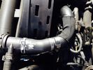
Thread upload18 viewsImage uploaded in thread 113360
|
|
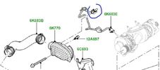
Thread upload7 viewsImage uploaded in thread 178898
|
|

Cooling System - Description and Operation 4.0L and 4.4L petrol engines 5 pages1009 viewsThis is a 5 page pdf that provides some insight into how the coolant flows thru all the hoses. Of interest is the paragraph,(page 3/5), that attempts to explain how and why the thermostat is designed to open at different engine operating temperatures - in brief, the reason for the spaghetti tangle of small hoses on the top of the engine.
There is also reference to an engine oil cooler that I gather cools something I think related to a supercharger, if fitted.
|
|

Thread upload2 viewsImage uploaded in new thread
|
|
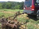
LR3 to plow your garden289 viewsI found this jpg where a current LR owner is using his LR3 for a similar purpose as the original Series units were designed to do - that is serve as a tractor for plowing a field or I suppose a garden.
In this case, I note the hitch is one of those that attach to the factory tow loop, (Rhino Hitch), rather than the factory product that inserts from the bottom and hangs down - (like a plow), but all the time. One of the other jpg's in this album shows the two factory variations plus a third jpg shows a closeup of the Rhino Hitch.
|
|

For those impressed by mechanical things...68 views
|
|
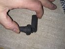
Sunroof drain hose10 views
|
|
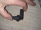
Thread upload13 viewsImage uploaded in thread 116740
|
|
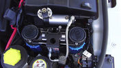
ARB CKMTA Twin Compressor178 viewsTwin Compressor with Manifold and Airtank. Tight fit but it fits. Also the ECU Chip is at the back and below up against the battery case.
I changed the hose quick release to a standard Air Hose Fitting eg like a workshop would use. My other truck has those also.
|
|
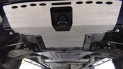
GOE Bash Plates117 viewsGreen Oval Experience Bash Plates. Front, Transmission and Compressor.
Might have to mod the front one a bit to let air into the trans cooler, it sits over the outside of the ARB bar which has vents for the cooler. If I cut slots in the Allow Plate to match those might do the trick.
I added a rear bolt to the Compressor Plate as it looked like it could get hooked on something and tear off. Two bolts onto the slider and two up onto the chassis now.
|
|

I want one of those61 views
|
|

Memorial to those who died during the war142 views
|
|
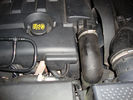
intercooler hose split49 viewsPART NUMBER PNH/500024 D05WA >CR<
FAULT CODE UNDER TDV6 DISPLAYED IS P0299 DESCRIPTION DISPLAYED UKNOWN BUT IS I THINK (UNDER BOOST)
|
|
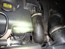
Split Intercooler Hose49 viewsPART NUMBER PNH/500024 D05WA >CR<
FAULT CODE UNDER TDV6 DISPLAYED IS P0299 DESCRIPTION DISPLAYED UKNOWN BUT IS I THINK (UNDER BOOST)
|
|

Vacuum Pump Upgraded Hose67 views
|
|

2nd Row footwell, showing water dispensing hose141 views
|
|
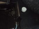
Internal 40 Litre water tank - top view of left side of tank105 viewsShows my spare tyre, but also bright white protective cap of top fill point and vent. Blue hose is water dispensing point. Note seat bracket bolt secures tank to D3. Similar bolt point on other side. Only these two bolts secure the tank and it is very secure.
|
|
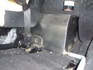
Left hand side of internal 40 Litre water tank161 viewsView from floor looking towards tank. Top white cover is 50mm plastic pipe cap. It protects the tank vent valve. Dispensing hose is at lower corner of tank
|
|
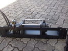
Hidden winch mount with winch in place122 viewsHydraulic hoses are now installed. Note notch for hydraulic:electric solenoid to fit in mount.
|
|
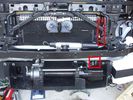
Installed winch with hydraulic hoses175 viewsThe hydraulic hoses are stiff, so I had to run them up the side of the radiator (can just see inside red boxes) to near the top of the radiator, then back down inside the engine compartment, then underneath the engine (behind the radiator) to the D4's power steering rack, where the hoses become metal. This hose routing may not be possible if the fuel-burning heater is in place (we don't have those in Aust and the space allowed room for my hands to bend and run the hoses without kinking).
|
|
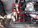
View of both hose connections to power steering system149 viewsBoth connections are shown. My friendly Qantas hydraulic hose expert cut off the elbow and modified it so I can re-install it to the PS rack before warranty work (and certainly before the vehicle is lifted off the body!!).
|
|
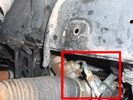
Further detail of attachment of the winch hoses to power steering system140 viewsThis is under the right (looking forward) lower plastic radiator cover.
|
|
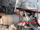
Detail of hydraulic hoses attached to power steering hoses153 viewsHoses are attached to the upstream side of power steering rack. When winch not running, PS rack sees full pressure (ie, no change from design). Biggest challenge is running stiff hoses so that they align with attach points. I got Qantas employee who repairs hydraulic baggage loaders to braise in fittings (very tight spaces and tough access).
|
|

399 viewsCloser view of leftside impact absorber. Note the thin piece of plastic I placed between the absorber and the cooling system component. Note air suspension hoses covered by protective tubing at bottom of photo.
|
|
429 viewsWasher bottle guard, I covered the exposed headlight waser hose with protective tubing.
|
|
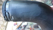
Intercooler hose - usual suspect20 views
|
|
Thread upload0 viewsImage uploaded in new thread
|
|
Thread upload0 viewsImage uploaded in new thread
|
|

Fuel Purge Valve and other hoses.838 viewsThis 6 page pdf shows the Fuel Purge Valve and associated hoses and describes how it is supposed to work. There are lots of good drawings of the fuel system. It is more complicated than one might think.
|
|
224 views
|
|

Flexible hose clamp plier20 views
|
|
Front Coupler pad to right front under air filter housing 155 viewsThe brighter white "square" behind the black air cleaner drain is the Coupler Pad location I chose for the right front corner. The 1/4", (5mm), black wiring loom carries a single blue colour conductor between the power supply and pad.
A second coupler pad, (white conductor), is located near the left rear tail light. The mounting location is accessible from the rear compartment access "door" where the trailer hitch wiring attaches to the factory loom.
|
|

Breather Hose exploded view.1207 viewsThis pdf shows the exploded view of the breather hose from the front differential to the engine compartment. The breather hose part number is TAP500081 and is identified as 4A058 in the drawing.
|
|
11 views
|
|
Thread upload5 viewsImage uploaded in thread 180378
|
|

Fix stiff gear selector or jumping out of drive into neutral32 viewsThis is a document culled from a topic about a simple fix to teh gearbox selector lever that fixes a problem with jumping out of drive into neutral.
I made the document to give to my local independent and thought it might be useful for others.
Thanks to disco_mikey, EdF and Robbie from the original post whose information and photos made this possible (I take no credit for anything here apart from errors).
|
|

Fix stiff gear selector or jumping out of drive into neutral17 viewsUpdated 19 Dec 2012
This is a document culled from a topic about a simple fix to the gearbox selector lever that fixes a problem with jumping out of drive into neutral.
I made the document to give to my local independent and thought it might be useful for others.
Thanks to disco_mikey, EdF and Robbie from the original post whose information and photos made this possible (I take no credit for anything here apart from errors).
Updated after I did this fix on my own car.
|
|
287 views
|
|
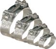
CLAMPS93 views
|
|

11 views
|
|
Thread upload7 viewsImage uploaded in thread 141499
|
|
Thread upload9 viewsImage uploaded in thread 148156
|
|
Thread upload8 viewsImage uploaded in thread 128413
|
|
Thread upload9 viewsImage uploaded in new thread
|
|

Thread upload16 viewsImage uploaded in thread 55010
|
|
Thread upload24 viewsImage uploaded in new thread
|
|

62 views
|
|

26 views
|
|
Thread upload8 viewsImage uploaded in thread 183363
|
|

Hose pinch off pliers20 views
|
|

53 views
|
|

68 views
|
|
Thread upload5 viewsImage uploaded in new thread
|
|
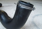
Split Intercooler Hose.95 views
|
|

New switch18 viewsNearly 5 years ago, I fiddled with some push-buttons, until one day I came across those marine Contura rocker switches :)
The remote control is the switch just behind the EPB.
|
|
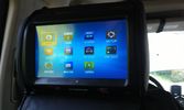
One of the multimedia headrests12 viewsI used to have seperate touchscreens mounted on the headrests.
I now went to the xtrons 9" headrests which gives the children the possibility to
- view whatever movie they want to
- listen to whatever music they want to
- play whatever 32native game they want to (although I'm not quite happy with those)
and they can do this no matter what the other one is doing :)
|
|
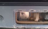
Outside connection to the compressor14 viewsFrom the compressor which is in the booth, the air hose runs to the back of the car.
I was able to install the connector in the space of the second trailer plug (which wasn't installed anyway).
|
|

33 viewsThe facia had some bits sticking out which fit quite nicely with the supplied double DIN support. As I was going to use the DIN supports supplied with either the radio and the CB, I needed to remove those bits sticking out. They made the DIN support bend as well.
|
|

An extra twist on running lights28 viewsAdded those nice 120mm LED rings on the covers of the roofrack lights and have them connected to my roofrack lights switch, as I wanted to control the LED manually as well (I don't believe this is 'road-legal', hence why I opted for the manual solution).
|
|
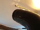
Have you seen the light?46 viewsHmmm... New hose please...
|
|
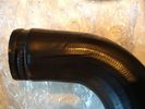
Let's Split!49 viewsNew hose please...
|
|
oil below small intercooler hose24 views
|
|

Grrrr, Air Line Hoses18 views
|
|
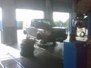
All four wheels off223 viewsHopefully the closest I\'ll come to the whole body off!
Note: Those aren\'t my new tyres.
|
|
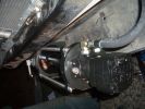
Hoses attached to motor475 views
|
|
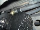
Motor with Hoses connected439 views
|
|

Switch is blue colour thing thru the rectangular opening.3149 viewsThe blue coloured plastic bit thru the rectangular opening is the brake light switch. The fist time, I found it easier remove the switch by dropping the horizontal plastic panel, (two screws), and then slipping my hand in and rotating the switch clockwise 1/4 turn. The second time, I was able to remove the switch thru the rectangular opening and did not need to remove the horizontal lower panel. Obviously, I had to remove the sloping knee pad panel, (note sort of hinged at the bottom so pull back from the top.)
Regardless, do not touch the brake pedal - just let it sit where it wants to. One has to first remove the angled knee pad panel that sits under the steering wheel. It can be pulled from the top corner at the door side. Pulling releases a pair of those U shaped metal clips that LR loves so dearly. You have to pull quite hard. The bottom is held by a couple of plastic fingers in a couple of slots so you pull at the top till the two clips release and then rotate the panel and pull upwards a bit.
To remove the switch, you rotate it clockwise and pull outwards. Rotating the switch clockwise automatically retracts the plunger back into the switch body away from the brake pedal arm.
Similarly when you install the new switch, the required 1/4 turn anti clockwise rotation action releases the plunger so it lays up against the brake pedal arm and at the same time, secures the switch in place.
To remove the electrical wires, the switch will drop below the horizontal pad and hang from the wires so unclipping the electrical connector plug is fairly easy to do.
|
|
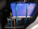
Blue tub contains Spares - hoses, belts, filters, fluids, wiper blades, etc176 views
|
|

Chief instructor (left) and another instructor explaining water crossings200 viewsWhilst no one tested the waters this time (they did last week with another group) you can just see the stick floating in the water (near second instructor's right elbow). Satisfied that the rains hadn't changed the depth dramatically, they let us through - those that elected to take the water crossing of course.
|
|

Last D3 through the deep crossing228 viewsThe water was stirred up by this time (didn't start off too clean due to heavy rains in the previous week) water was between 500 and 600mm deep depending on where the driver crossed. Away from the tree was slightly deeper but most drivers chose that line to be well clear of the tree.
|
|
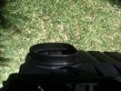
Half way finished cutting aibox inlet with Dremel - as it was too large to fit the 83mm flexible hose onto it.161 views
|
|
Cut out of inner guard completed - to allow 83mm flexible hose through, as the smaller hole in channel was too small.164 views
|
|
Looking down at jubilee clamp holding flexible hose to airbox inlet.183 views
|
|

Those holes needs to be bigger43 views
|
|

A nice piece of kit...349 viewsOne piece of kit I bought for myself. A backpack big enough for one of those 17" MacBook Pro from Apple which does also possess some solar panels to recharge the batteries in my Treo, my BT GPS or iPod. Convenient for when I am NOT in the car... Here the background is an armored Toyota... No Landies around ! :-(
|
|
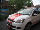
The Wifes, she made me get those stripes 87 views
|
|

extension hoses56 views
|
|
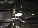
5 viewsBlown turbo hose causing the engine to cut out every time you try and over take or climb a hill. Have a new Samco kit to go on at some point.
My super bodge works a treat.
|
|
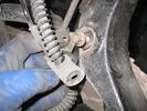
hose and so on removal68 views
|
|
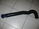
silicone IC hose34 views
|
|

IC hose lower clip46 views
|
|
Split intercooler hose97 viewsCaused black exhaust smoke when power was applied
|
|
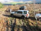
He's out there somewhere...137 viewsHobgoblin - vainly searching for the D3 skipper who chose to go down with his ship...
|
|
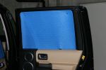
Rear Right212 viewsQuality. Made to measure. Making the template was the hardest part. Absolutely ZERO light ingress through these blinds and keeps those who go dogging out too.
|
|
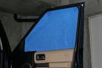
Front Right215 viewsQuality. Made to measure. Making the template was the hardest part. Absolutely ZERO light ingress through these blinds and keeps those who go dogging out too.
|
|
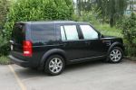
Side Windows233 viewsQuality. Made to measure. Making the template was the hardest part. Absolutely ZERO light ingress through these blinds and keeps those who go dogging out too.
|
|
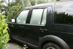
Side Windows166 viewsMade to measure. Making the template was the hardest part. Absolutely ZERO light ingress through these blinds and keeps those who go dogging out too.
|
|

Big those twenties ! 275 40 20 !268 views
|
|

Freelander 2 SD4 HSE15 viewsThe missis chose it and was a bit upset when I traded it in for the Disco, she's ok with it now the Disco is growing on her!
|
|
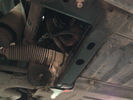
undervody with old intercooler hose9 views6 years and 92,000 kms later, my intercooler hose was about to be replaced
|
|
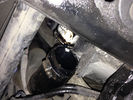
old intercooler hose9 views
|
|
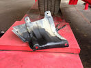
this is how the underbody looks like with my old intercooler hose10 views
|
|
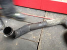
intercooler hose pic 28 views
|
|
old intercooler hose9 views
|
|
Thread upload16 viewsImage uploaded in thread 132186
|
|
Thread upload12 viewsImage uploaded in new thread
|
|

pipe121 viewsThis shows the pipe I thought was the sunroof hose.. hope it was the water jet hose
|
|

Thread upload13 viewsImage uploaded in thread 55010
|
|

Thread upload19 viewsImage uploaded in thread 127167
|
|

LR3 Air Conditioner Drain Tubes behind centre console2091 viewsThis shows the two air conditioner drain tubes located left and right under the radio stack.
The tube on the left side, (steering wheel side, LHD), disattached itself and the carpet on the floor under the gas pedal etc became soaked. I think rain water from outside that comes in the outside cowl vents also exits via the tubes as I first noticed the carpet was wet after parking outside during a big rain storm.
It was relatively easy to slide up and reattach the rubber hose that runs from the rectangular shaped plastic discharge hole(s) of the heater "pan" down along the transmission hump area and thru the floor pan. There is a hose on each side of the transmission hump, but only one hose had let go on my 3. The rubber hoses just slide over the rectangular plastic openings of the two heater housing drain outlets.
To get at each drain hose, remove the vertical sort of triangle carpeted piece below each side of the radio stack. The triangles of carpet will just pull away as each is held on with those metal U clips Land Rover so likes. Dislodge each triangle at least sufficiently to get ones hand in to slide the rubber hose back on.
You will rarely see AC water on the ground as the front drains pour onto a metal underside protection skid plate and the rear drain onto the top of the left rear muffler.
|
|

Horn Wiring Circuit LR3575 viewsThe is the wiring diagram for the dual horn circuit.
The Horn Relay, (R133), is not a big black thing hidden somewhere but instead what is called a FET, (and it is hidden)!
This is a Field Effect Transistor that is built into the circuit board that is mounted to the back of the fuse box that is located behind the lower glove box door on the passenger side of the 3. The related 15 amp fuse, 12P, is mounted in this fuse box and is often called F12P, where F is for fuse, and P is for Passenger compartment.
This is to help differentiate from another fuse and relay box, (the usual kind), that is located beside the starting battery in the Engine compartment. FxxE is often used in the naming of those fuses.
|
|
Pressure hose from psp53 views
|
|
Thread upload7 viewsImage uploaded in thread 173156
|
|

G4 side on145 viewsStill not sure about those wheels, I fancy a set of std HSE wheel with MTRs just as it should be
|
|

Thread upload16 viewsImage uploaded in new thread
|
|
Thread upload13 viewsImage uploaded in new thread
|
|

231 viewsRedneck encounter - check out those mud socks!
|
|
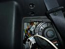
rear socket install1386 viewsTraxide rear socket installation, alternative location. These holes must be precisely in this location because there is little clearance to the right of left due to the blower motor and hoses, etc.
|
|
Top view air hose210 views
|
|
Turbo Change18 viewsTurbo hoses were upgraded to silicone jobbies
|
|
256 viewsSystem testing. Nothing caught fire, which is a success in my book! Just know that the rover gets very angry when all of those control panels are disconnected.
|
|
204 views
|
|

Pumas - for those with an average of 2 feet181 viewsSpotted in Cairns whilst visiting the Great Barrier Reef. Suppose it must be a translation from Chinese that results in such mirth.
|
|
Thread upload0 viewsImage uploaded in thread 197284
|
|
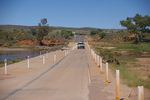
Hey Jonesy! Watch those pot holes108 views
|
|
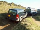
My D3 safely at the top of Roych Steps221 viewsWhistled up with little drama - lost a bit of momentum coming up to the last couple and needed a couple of goes to get up them.
For those there in July - this is a completely different kettle of fish when going up it!
|
|
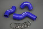
Thread upload35 viewsImage uploaded in thread 94971
|
|
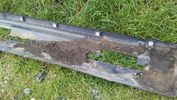
Door Sill9 viewsLook what lurks behind those rugged plastic sill trims. Here's the muck gathered over the years, damp and sitting against the metal body
|
|
split hose36 views
|
|
Thread upload1 viewsImage uploaded in thread 56379
|
|

What are these?206 viewsWhat are those green things with long thin pointy bits sticking out of the front?
|
|

73 views
|
|
62 views
|
|
62 views
|
|
73 views
|
|
216 views
|
|
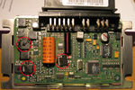
transfer case control module71 viewsPicture shows blown components of the Transfer Case control module after water ingress over time - with a healthy top up from over-enthusiastic lad with a high pressure water hose in the car wash!!!
|
|
Thread upload24 viewsImage uploaded in thread 156013
|
|

Thread upload15 viewsImage uploaded in new thread
|
|
Thread upload4 viewsImage uploaded in thread 71668
|
|

Varta Battery Dimension chart568 viewsThis pdf provides Varta dimensions for among others, the E12V75N, (old DIN H6 or 85605 or BCI Group 48 size). This appears to be a deep cycle battery and the choice for many re the Aux battery install as long as you are willing to grind away the angled nibs at the bottom front of the battery surround. My choice was a shallow cycle battery intended for cold weather related engine starting rather than winch use.
Note the pdf Varta batteries are all deep cycle batteries suitable for running fridges, winches etc, rather than for engine starting and hence a good Aux battery if those are the intended uses rather than engine starting.
Varta now makes a Varta G14 with AGM technology and known as a Stop Start Plus battery. It is 95Ah, CCA of 850A; length 353mm; Width 175mm; Height 790mm and is specific for these newer stop start vehicles such as some D4's. For the 3's, one is still probably better off with an H8 sized battery but of the older Wet Flooded Lead Acid type and battery caps rather than a sealed AGM.
The Land Rover part number for the recommended battery is LR033179.
|
|

Thread upload3 viewsImage uploaded in thread 195348
|
|

MS Word Keyboard shortcuts151 viewsFor those that prefer to use keyboard shortcuts when working with MS Word - here is one I prepared some years ago.
|
|
|
|
|
|