| Search results - "internal" |

238 viewsThe roof panel (inside) with the internal bracket
|
|

Internal window blanks136 views
|
|
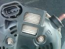
Alternator Plug and B+ terminal910 viewsPictured is the rear of the older Land Rover part # YLE500190 alternator showing the shiny cooling fin of the Regitar VRH2005-142 regulator under.
The first pin in the far left side of the connector is numbered #1 in the LR electrical wiring diagrams and is Battery Voltage Sensing (BVS); the middle pin, #2 receives a Pulse Width Modulated (PWM) signal from the Engine Control Module (ECM), and the right pin, #3 carries a PWM signal back to the ECM. Terminal Pin #2 on the LR wiring diagrams is called Alternator Control or ALT CON; Pin #3 per LR is called Alternator Monitoring or ALT MON.
Pin #1 is similar to what in older designs used to be called A or Batt, but is now called by Denso, S, AS, or Alternator Sensing for this design. Pin #1 also provides power to excite the alternator at startup until the PWM instructions over ride the battery voltage info. Land Rover calls the electronics under the pins a Smart Regulator, ironic, as it has to follow orders from the ECM rather than give the orders - new age thinking I guess. This is different from older design internal regulators that look at just the battery or the electrical buss voltage and then decides itself what to do.
It is almost like we are back to the external regulator designs of old, except that the ECM may decide that instead of telling the alternator to make more power, to load shed, and hence shut down the heated windscreen, seats, or whatever other electrical loads it decides are appropriate. My view is that the "smarts" are in the ECM and that the "regulator" should be regarded if not dumb, then as being a slave to the ECM.
|
|
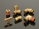
Detroit Fluid DOT air line fittings716 viewsThe picture shows the internal ferrule that is characteristic of the DOT / TUV accepted fittings for highway vehicles. Most often these fittings are metal however the Land Rover John Guest 6mm straight connector is all plastic and has the internal ferrule.
|
|
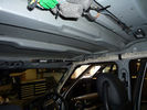
Roof Rail Failure Internal93 views
|
|
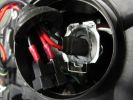
D4 hid internal connections198 views
|
|

Defender31 viewsInternal Defender mirror
|
|

Defender31 viewsInternal Defender TrailAir mirror
|
|

The Test Rig272 viewsDiscovery TDV6 SE - Adriatic Blue, Alpaca
Caravan - Future System Full Fibreglass (one piece) 21ft (6.10m)internal length
|
|
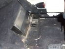
Internal water tank right side view160 viewsShows right front side of tank, with RH seat lifted. Note seat bolt is used to also hold the tank secure. This is a 5-seat D3, which has a cover over what is normally the 3rd row footrest. This is where the water tank is located.
|
|
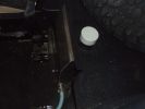
Internal 40 Litre water tank - top view of left side of tank105 viewsShows my spare tyre, but also bright white protective cap of top fill point and vent. Blue hose is water dispensing point. Note seat bracket bolt secures tank to D3. Similar bolt point on other side. Only these two bolts secure the tank and it is very secure.
|
|
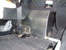
Left hand side of internal 40 Litre water tank161 viewsView from floor looking towards tank. Top white cover is 50mm plastic pipe cap. It protects the tank vent valve. Dispensing hose is at lower corner of tank
|
|
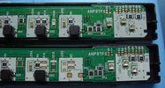
Forward Alert switch internals42 views
|
|
Thread upload2 viewsImage uploaded in new thread
|
|
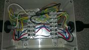
Topside123 viewsWiring from the top, one additional earth added to the internal box after the picture was taken.
|
|
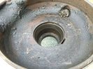
Rusty diff internal20 views
|
|

LP scoped 218 viewsBy connecting a Low Amps probe to the fuel pump's voltage supply wire, you can view the pump's current waveform on a digital storage oscilloscope (DSO). The scope pattern will reveal internal wear in the brushes and commutator that may not show up in a traditional pressure or volume test.
Observing the waveform will show if the pump's amp draw is normal for the application or is high or low, and if the pump is operating at normal speed or is running slow. Problems such as a bad spot on a commutator or a short or open in the armature also will be obvious in the waveform.
A "good" electric fuel pump waveform will generally seesaw back and forth with relative consistency and minimal variation between the highs and lows. A "bad" waveform will show large or irregular drops in the pattern, with large differences between the highs and lows.
|
|

Internal heating element fastend with 3M Dual Lock 44 views
|
|

Placement of internal heating element44 views
|
|

Placement of internal heating element44 views
|
|
Thread upload0 viewsImage uploaded in thread 184905
|
|
Thread upload1 viewsImage uploaded in thread 184905
|
|
Thread upload1 viewsImage uploaded in thread 184905
|
|

Thread upload5 viewsImage uploaded in thread 108682
|
|
Thread upload6 viewsImage uploaded in thread 200461
|
|

Interstate Battery Dimension sheet640 viewsThis sheet is hard to find - the sheet is not on the Interstate corporate web site but some dealer web sites display it. The pdf shows most of their available batteries including the H7 and H8 sizes that are the LR North America replacement batteries for the main starting battery. These batteries are of the Land Rover desired "shallow" cycle high discharge current Maintenance Free, (Ca Ca), internal construction, (not AGM, but instead, Wet Flooded Lead Acid with battery "caps" and Ca grid separators).
For the AUX battery , the H6, (BCI Group 48), is probably similar in dimensions to the Varta E12V75N that is popular in Australia. For that battery to fit in the second battery compartment, you must grind out the angled nibs on the inside front bottom of the LR black plastic surround, something I did wish to do and hence installed a Group 40R on a spacer. Alternately, one can choose an Interstate BCI Group 47 which is similar to a DIN H5 for the AUX location. I did this when I had to replace my 40R. No vertical spacer is required and the stock battery tie down bolts and clamp work well.
|
|

LA100-005 - Technical Bulletin - Internal Control Module Faults Relating to the ABS Module Diagnosis83 views
|
|

Air Suspension ECU Fuse 35P Shut Off Switch2623 viewsA more distant view of the shut off rocker switch in the ON position which is the normal position for when all is working as Land Rover intended.
Ideally, (but not totally necessary), the F35P circuit should be powered or de-energized after the various computers have gone to "sleep".
Similarly, removal of the F26E or F3E fuses is preferable after the computers have all gone to sleep but it appears that no real damage will be done if the fuses are removed while the system is energized. Pulling F26E is the main full time fuse that powers the air suspension computer. As such, once F26E is removed, pulling F3E is not really required.
Power for the compressor goes thru the 60 amp fusible link and relay, however control of the relay is via the air suspension computer so depowering the air suspension computer effectively depowers the air compressor and the internal exhaust valve relay/port.
|
|
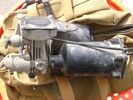
Compressor Air Drier 2040 viewsA view of the air drier - the black round thing to the right of the actual compressor cylinder head.
The general feeling is that the air dryer is responsible for most of the compressor problems now and that replacement of either the assembly or just the beads inside will probably revive one's compressor. In reality, the beads may have for the most part broken down and turned to dust plugging the internal filters. Hence replacement of the complete dryer unit has some merit.
The part number for the dryer assemble complete with the desiccant is VUB504700.
|
|

LR3 Denso Alternator YLE500390 pulley view817 viewsNote the DENSO sticker on the side. Denso calls their nominal 150 amp 12 Volt alternator an SC2 design. SC means Segment Conductor which apparently increase the winding density of the stator coil, hence yielding a physically smaller lighter alternator for a given output. I presume the 2 means the second try at getting it right. A Denso part number is 4280003690 for the alternator, (there are others, as below).
Rotation is clockwise and the 54mm diameter pulley has 6 grooves (PV6x54). Count the pulley grooves on both the one you remove and your new one - some replacement alternators seem to ship with 5 or 7 grooves so you might be swapping pulleys.
A previous LR part number was YLE500190 for the older variation of the newer YLE500390 unit.
An additional part number for a factory rebuilt is Nippon Denso 210-0569 for the petrol V8 alternator. Other Nippon Denso numbers include 104210-3690 and 104210-3691. The Lester number is 11206 which relates to another Denso number of 290-5287. WAI uses 11206N.
From 2006 to 2009, the internal regulator is a Transpo IN6349 and of the B circuit type if it can be said that applies to PWM, (Pulse Width Modulated), regulators.
The "regulator" inside the alternator is therefore really not a regulator in the old sense of the term but instead an instruction receiver from the ECM that translates Pulse Width Modulated (PWM) signals into a form that the alternator understands – digital like signals from the Engine Control Module(ECM) into analogue like signals that the windings understand.
|
|

Fuel Tank Internals, Description and Operation 804 viewsThis 10 page pdf shows views of the fuel tank internals, what the various pieces do and describes how the fuel storage system is supposed to operate.
As usual, you can download it, save, and print as required.
|
|

Magcode power port90 viewsmagnetically held together, low profile internally and externally.
|
|

Thread upload1 viewsImage uploaded in thread 198799
|
|

Clarke CTJ3000QL and Threaded Saddle61 viewsWith the saddle withdrawn (after removeal of grub screw) it has a 25/26mm internal thread diameter - thus by my reckoning an adaptor lug should be 25mm diamater
|
|
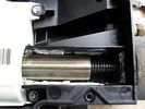
Now we are getting to it...439 views... the threaded (or DREADED) actuator - externally splined internally threaded element (centre of pic) rotated by gearbox (on left of pic) to pull cable end (externally threaded, on the right)
|
|
Thread upload4 viewsImage uploaded in thread 114031
|
|

D3 Fuel Tank Internals28 views
|
|
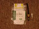
Voss System 203 connector 6 mm for valve blocks 900 viewsThis is Land Rover part number RQC000030, the Voss fitting for the axle valve blocks. I think it is a Voss System 203 6mm fitting, Voss part number 5 2 03 11 01 00.
The parts bag comes with the white plug inserted in the brass threaded bit with what is called the brass cutting ring placed on the tip of the white plastic plug. The idea is that one screws, (M10 x 1 thread), the brass insert into the appropriate hole with the white plug still in the brass insert. Once the brass is tight, (12 mm wrench), then the white plug is pulled from the assembly leaving the cutting ring down inside and under. One then pushes in the 6 mm tube end about 20 mm or so and the tube slides down thru the brass cutting ring, (2 internal sloped one way cutting ridges). When the tube is in far enough, one pulls upwards a bit and the ring cuts into the plastic such that the tube will not pull out. To remove tube, one unscrews the brass nut and all comes out, sort of like I have shown with the short piece of 6mm tubing. The white plug is a throwaway item upon install of the tubing.
|
|

Electrical Connector Sleeve Replacement ZF 6HP26959 viewsThis 3 page pdf with pictures shows how to replace the sleeve that holds the multipin electrical connector that passes thru the transmission body to the Mechatronic unit.
The install of the sleeve is more difficult than the removal in that one must not rotate the sleeve as damage to the internal pins can result. The pan must be first removed to both remove and install the sleeve.
|
|

Mechatronic Sleeve Removal and Install Instructions1042 viewsThis 3 page pdf with pictures shows how to remove and install the Mechatronic sleeve that tends to leak tranny oil after about ten years. Even if not leaking, replacement when doing a pan/filter change at the ten year mark is suggested.
Note the 3mm or less requirement when sleeve installation is completed; also that rotation of the sleeve during the install procedure can do damage to some internal pins - hence do not rotate the sleeve when trying to insert it or in getting it to lock in place - not so easy it seems.
|
|
|
|