| Search results - "iron" |
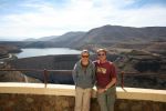
Ironman & IronWoman @ Katse Dam157 views
|
|
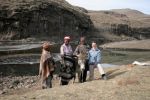
Ironwoman doing what she does best.. helping the locals128 views
|
|
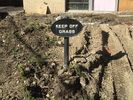
Irony320 viewsSelf Explanatory, there is no grass.
|
|
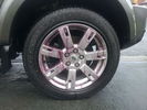
Iron X41 viewsCar Pro Iron X making the wheels bleed - absolutely stinks
|
|
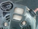
Alternator Plug and B+ terminal910 viewsPictured is the rear of the older Land Rover part # YLE500190 alternator showing the shiny cooling fin of the Regitar VRH2005-142 regulator under.
The first pin in the far left side of the connector is numbered #1 in the LR electrical wiring diagrams and is Battery Voltage Sensing (BVS); the middle pin, #2 receives a Pulse Width Modulated (PWM) signal from the Engine Control Module (ECM), and the right pin, #3 carries a PWM signal back to the ECM. Terminal Pin #2 on the LR wiring diagrams is called Alternator Control or ALT CON; Pin #3 per LR is called Alternator Monitoring or ALT MON.
Pin #1 is similar to what in older designs used to be called A or Batt, but is now called by Denso, S, AS, or Alternator Sensing for this design. Pin #1 also provides power to excite the alternator at startup until the PWM instructions over ride the battery voltage info. Land Rover calls the electronics under the pins a Smart Regulator, ironic, as it has to follow orders from the ECM rather than give the orders - new age thinking I guess. This is different from older design internal regulators that look at just the battery or the electrical buss voltage and then decides itself what to do.
It is almost like we are back to the external regulator designs of old, except that the ECM may decide that instead of telling the alternator to make more power, to load shed, and hence shut down the heated windscreen, seats, or whatever other electrical loads it decides are appropriate. My view is that the "smarts" are in the ECM and that the "regulator" should be regarded if not dumb, then as being a slave to the ECM.
|
|

Thread upload4 viewsImage uploaded in new thread
|
|
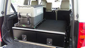
Ironman Drawers and Fridge Slide111 viewsI hate kitsets, over 100 bolts to assemble this unit and lost gallons of sweat, must have read the instructions a hundred times or more but final product does not look so bad. A few bolts hanging out the sides of both slide and drawers that may catch things so time will tell if I made the correct purchase.
Maybe one day I will make some side wings to cover the sides properly.
|
|
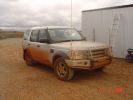
Iron Ore Dust, Newman WA97 views
|
|
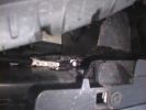
The swinging lump of iron that sit under the back,867 viewsLook how close it is to the wiring!
|
|
399 views
|
|

Fraser Island Camping Map165 viewssource courtesy Environmental Protection Agency
|
|
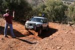
Ironwoman going through the paces123 views
|
|

Salisbury Plain299 viewsMy other club (Range Rover Register) had a plains day, ironically none of the 5 vehicles present were RR but 3 were at least from the same factory!
|
|
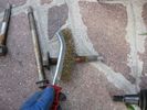
iron brush bolt65 views
|
|
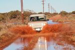
CALENDAR 2008 ENTRY705 viewsfollowing the Iron Duke railway to check out the damage after some heavy rainfall.
|
|
Thread upload30 viewsImage uploaded in thread 104311
|
|
Thread upload7 viewsImage uploaded in thread 140859
|
|

Thread upload2 viewsImage uploaded in thread 183933
|
|

Thread upload16 viewsImage uploaded in new thread
|
|

83 views
|
|

Thread upload0 viewsImage uploaded in thread 204242
|
|
Thread upload4 viewsImage uploaded in thread 180399
|
|

Thread upload5 viewsImage uploaded in thread 159579
|
|

Stop Light Lamp Circuit pdf2461 viewsThis pdf shows the brake light circuit for the NAS LR3.
Note that power for the brake light bulbs can come either thru the brake light switch power feed /contacts plus also from the Hill Decent Control, (HDC), system relay located within the Central Junction Box, (CJB) - yes two separate sources of power for the brake light bulbs. This would tend to explain how a brake light circuit concern shows up as a hill decent fault message; also why lesser vehicles without hill decent braking mechanisms, (HDC), never display this sort problem when a brake light bulb or switch acts up. You never have a problem related to a system that does not exist.
Additional evidence of the relationship of the HDC and the tail light circuit is demonstrated by when the HDC actually acts to slow the 3 down, the brake lights automatically illuminate even if the slowing action was merely retarding the engine speed or shifting to a lower gear, (in other words, no foot on the brake pedal).
There is also a tie in to the Cruise Control and hence a failing brake light switch can affect cruise operation or just create false Cruise Control messages. To further complicate the issue, while there are no messages generated, operation of the radiator electro viscous fan can also be negatively affected by the fouled set of secondary contacts within the brake light switch. This is all because the NC contacts within the brake switch send misleading messages to the ECU.
While the ground wire design is similar to other vehicles, note the grounds for the brake light filament and the reverse light filament are common on each side. That means that if one has a non functioning brake light on one side, the reverse light may not also work or that some problem with the reverse lights could back feed into the brake lights. This situation while unusual, can result when grounds are corroded probably due to swimming in rivers and creeks or just routine driving in a marine environment.
|
|

142 views
|
|
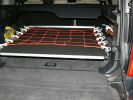
Sliding floor - closed position514 viewsMaterials: 17mm formply, ex 1000mm piano hinge, 2x Haefele 160 kg sliders, timber brackets for the floor to connect the sliders, aluminium angle for leading edge, 50x3mm aluminium flat drilled for the tie-down net connectors, 2x galv iron flat folded to form angle brackets (to secure sliding loadspace to floor), 1 square metre of black carpet to match the back of the seats.
|
|
Reinforcement angle iron37 views
|
|
Thread upload17 viewsImage uploaded in thread 131089
|
|
Sump plug - Rear diff80 viewsSump plug - Rear diff. Check all the iron filings
|
|

23 viewsTo be Auctioned.
Framed 'Iron" Mike Tyson Autographed Help for Heroes T-shirt From the October 2012 UK tour, Two only like this ever to be done.
All money raised goes to Help for Heroes.
|
|
Thread upload4 viewsImage uploaded in new thread
|
|
Thread upload6 viewsImage uploaded in new thread
|
|
Thread upload6 viewsImage uploaded in new thread
|
|
Thread upload6 viewsImage uploaded in new thread
|
|

IronMan 2008 finish112 views
|
|
|
|
|