| Search results - "led" |

112 views
|
|

0000 LR Bluetooth dealer Kit install instructions1583 viewsThis 17 page pdf is mostly a series of pictures showing how to install the original Land Rover dealer installed Bluetooth kit for circa 2005 / 2006 three's. Also included are three wiring diagrams sheets related to the pairing code 0000 Bluetooth install.
This pdf is useful if you are now removing the 0000 kit to install the optical 2121 MOST D4 module, an easier install than the 0000 kit ever was.
|
|
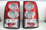
D4 LED Lights91 views
|
|

D4 LED Lights77 views
|
|

For all those SWMBOs - a place called SHOP101 views
|
|
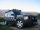
CALENDAR ENTRY 20091190 viewsBonatti grey TDV6 S, ambulance conversion, MTR's, winch, RAI, safety devices roof rack, rear ladder, bash plate, warn lighting, LED lighting throughout.
Owned by me, Rich Bell, Director of Extreme Medical Ltd, providers of medical support to Land Rover events.
|
|

This is why the bus was canceled!38 views
|
|
Arches rusting - now undersealed100 views
|
|

Arches rusting - now undersealed92 views
|
|
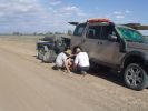
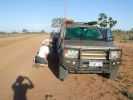
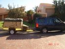
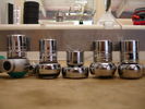
03 The first bit of tyre/wheel problem249 viewsSomewhere in the Australian outback on a 45 deg C day in Jan 08, a D3 had a bit of a flat tyre problem. "No worries, mate" st we had 3 spares (plus 2 more if we abandon the trailer), 150l of water, 4 days of food, and an EPIRB if things really go crook. The first clue that this was not a "normal" flat was when I handled a wheel nut and ended up with a blister from a burning hot nut (the ambient wasn\'t THAT hot).
|
|
408 views
|
|
478 views
|
|
Here it is - long awaited Mantec plate in action directly after being installed! Thanks again John!!!169 views
|
|

07 Back side of failed tyre340 viewsThis is the back of the blown tyre. It looks like any other worn tyre which has run a bit while flat. Note that we were running on wider 19" RRS wheels (have 4 19" MTRs + 1 old A/T on the original 5 wheels). Also have a rear-mount spare tyre holder which is really convenient with the wider rim and the fact that the tyre was still hot (it had some melted rubber on the other side!!)
|
|
08 D3 stranded with a seized smoking wheel314 viewsAbout 1 hr after replacing the blown tyre, strange noises emanated from the stability control system and speed dropped off. Then I looked in the rear view mirror, and noted a cloud of dust along with a whiff of black smoke. This led to a very quick stop (no traffic on this route for over a week, so no worries about having to signal exiting the road). Took a look and WOW. The right rear wheel was glowing a dull red colour, and burning rubber smoke was wafting from the red glow over the fuel lines.
|
|
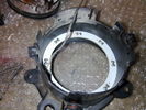
led fog54 views
|
|
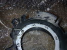
LED light56 views
|
|
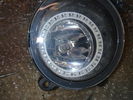
LED light63 views
|
|
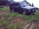
Almost a roll, but not quite...55 viewsI\'d \'launched\' myself at a 6ft hill and got to the top- but at an angle- the offside rear gripped and pulled us around to the right- perilously close to the edge... time for spare undies I think...
|
|
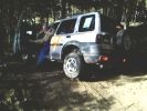
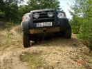
Freelander trying hard.107 viewsStill not stuck but getting there. In the end pulled it out with a Defender. Picture taken at Offroad-Training in Linthe/Germany
|
|

Crumbled sleeve 28 views
|
|

09 Starting to remove the seized brake assembly295 viewsBy this time we\'d poured about 8l of water on the dull-red glowing and burning wheel assembly (too close to 140l of 98 octane petrol). Sudden cooling cracked the disk brake which showed mangled park brake parts. How to remove a brake disk without the right star fitting? First remove the caliper then get a sledge hammer?!!
|
|

A few mods later26 viewsPro-Speed rock/tree sliders
LED side lights
LED interior lights
|
|
![Filename=0_90895_892fd502_L[1].jpg
Filesize=53KB
Dimensions=500x306
Date added=05.Nov 2013 0_90895_892fd502_L[1].jpg](albums/userpics/38239/thumb_0_90895_892fd502_L%5B1%5D.jpg)
only leds14 views
|
|

10 Cracked smoking parking brake drum337 viewsNote the crack in the face of the brake. This showed mangled parking brake springs and other bits. Also a bit of melted rubber was drooling out of the crack. Started to remove the brake caliper and enjoying the flies in 45 deg C heat. Ah, the wonderful Aussie climate in January.
|
|
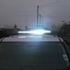
SR 30 inch led lightbar57 views
|
|

Bracket drilled and fitted217 views
|
|

Attuatore rimontato - Actuator reassembled40 viewsAttuatore rimontato col cavo di emergenza.
Actuator riassemble with emergency cable.
|
|
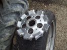
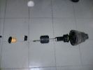
What was left24 viewsThe bitty which was left attached to the hub when the wheel failed whilst driving
|
|
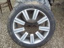
Front View33 viewsShowing the wheel which failed whilst driving.
|
|
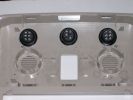
195 viewsSwitches installed in the roof panel
|
|

234 viewsThe cable loom for the lights (installed by 10forcash)
|
|
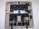
221 viewsThe complete roof panel reassembled
|
|
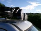
261 viewsOriginal Frontrunner brackets, but installed upside down to reduce the total height
|
|
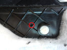
Foro pannello - Panel hole40 viewsHo forato il pannello moquettato per far passare il cavo di emergenza.
I drilled the carpeted panel to drive the emergency cable.
|
|
Thread upload1 viewsImage uploaded in thread 5
|
|

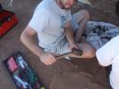
12 Half way through removing a jammed disk brake in the Outback296 viewsThis was just before breaking the sledge hammer. Note we luckily carried a spare hammer. Ended up using (or breaking) every tool we had on this little repair job. Bed sheets are a good way of gathering the bits to show for the inevitable warranty claim.
|
|
13 How to care for tools302 viewsWhat happened to the sledge hammer after 2 hours of beating my seized and cracked disk/park brake assembly to bits. Now down to 1 hammer remaining. At least by this time it was getting cooler (down to 40 deg C)
|
|
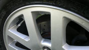
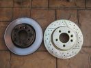
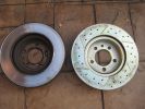
55 viewsDrilled and vented disks
|
|
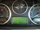
fuel range????????294 viewsfilled tank up and climbed the 21 hairpins into Alpe d\'Huez 1860m - as you can see the projected fuel range (due to the climb) suffered. The reality was different as it used virtually no fuel on the descent.
|
|
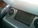
Geosat2 GPS installed498 views
|
|
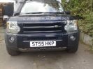
led left133 views
|
|
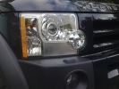
led close173 views
|
|
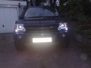
ledlights155 views
|
|
led with guards140 views
|
|
Thread upload1 viewsImage uploaded in thread 5
|
|
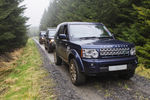
D4 HSE Kileder Safari170 views
|
|
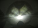
This is a normal H7 HID bulb installed in a BMW headlight to show glare above cut off line96 viewsThis is what the light pattern is that causes glare in most retofit applications including some projector lights. this is in fact a projector headlight on a BMW but the old projectors were only actually half projectors and half reflective bowls. the beam pattern should be clean cut like this ___/
|
|
Thread upload1 viewsImage uploaded in thread 5
|
|
Remove Headlights and Grille using bulb replacement instructions in Manual - Push the fixings supplied into these holes circled in red148 views
|
|
Holes drilled and spacers positioned for the latch plate278 views
|
|
Drilled all round the marked pattern inside then used Dremel to cut out neatly810 views
|
|
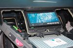
108 viewsTest fitting the screen. The bottom edge of the rear cover of the screen has been already dremeled off in this pic, notable as the circuit board can be seen.
|
|
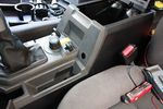
76 viewsDrilled hole for switch
|
|
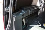
78 viewsHole for 12V accessory socket. This hole has a blanking plate on it on Commercial D3s. It just needed to be filed down in some areas to fit the socket I bought.
|
|
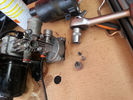
Compressor disassembled41 views
|
|
Nut disassembled32 views
|
|
TravAll Dog guard installed and waiting for passengers163 views
|
|

LED Reverse light53 views
|
|

Original Reverse light52 views
|
|

Opaque switch cover116 viewsKR switch on:off:on used for front and rear spots - but LEDs not visible with coloured switch cover!
(Located in sunroof switch position)
|
|

KR switch with drilled holes118 viewsResults of drilling holes in opaque switch to see LEDs. Simple ideas can be the best - thanks Dad!
|
|

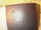
KR switch cover drilled115 viewsNow I can see the LEDs underneath!
|
|
31 viewsLed sidelight and 6000k xenon
|
|
39 viewsLed sidelight and 6000k xenon
|
|
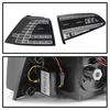
Thread upload0 viewsImage uploaded in new thread
|
|
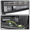
Thread upload0 viewsImage uploaded in new thread
|
|
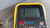
Resistance Ohms Failed glow plug10 views
|
|
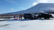
Familly sledging with the disco24 views
|
|
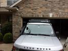
low profile solar panel203 viewsThe low profile solar panel, can be seen here, as the fine white line under the light bar. The way it's laid out, the panel should generate decent power between 10am and 4pm depending on the time of year, from the sides or front, with no shadows. Grape Solar 100W flex panel.
https://www.facebook.com/DifferentialPartsUS
|
|
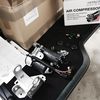
new parts waiting to be installed2 viewsImage uploaded in thread 177818
|
|
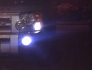
LED fog55 views
|
|
LED fog65 views
|
|
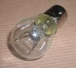
Land Rover Stop Tail Light dual filament bulb nominal 12 volt 21 / 5 watt filaments1412 viewsThis is the Land Rover part number 264590 dual filament bulb, (P21/5), that inserts into the upper two tail lamp receptacles. In the upper one, both filaments function, in the lower one, only the 5 watt tail light filament functions.
I regard it as not a good practice to routinely switch bulbs when the tail light filament, (5 watt), burns out on the lower bulb. The broken filament can jiggle over onto the brake light filament, (21 watt), and short the circuit to ground or something else not predicable.
There are also arguments to say that quality control is better on the Land Rover marketed bulbs than say far east sourced bulbs. Filament construction, and hence resistance can vary and mislead the current sensing circuits monitoring the signal light systems. Also when the bulbs are properly installed, all filaments should be standing vertically and not at any slope.
These are the sort of obscure circumstances that can lead to false trouble messages on the display, dropping to the stops, and subsequent concerns - all over a tail/signal light bulb.
For example, the filament life of both the tail light and the brake light filaments in the P21/5 bulb is significantly less than the USA common 1157 dual filament bulb, (1000/250 vs 5000/1200 hours); brightness in the P21/5 is a bit more, (3cp/35cp vs 3cp/32cp where cp is candle power), but current consumption is oddly less, (0.44a/1.86a vs 0.59a/2.10a where a is amps). It is the quest for efficiency vs maintenance trade off.
|
|
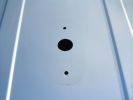
3 GPS/Telephone Pre drilled Holes60 views
|
|
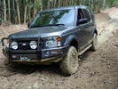
fun in the mud316 viewsCALENDAR ENTRY 2011
This is in Puerto Rico. The area is called \'cielito\' (little sky).
|
|

204 views
|
|
Thread upload1 viewsImage uploaded in thread 5
|
|
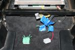
04272 viewsThe green wiring harness is the speaker outputs. Green is + and Green with white stripe is -. We tested all the wires with a 9V battery to figure out which went to what speakers then clearly labeled them as we did.
|
|

57 views
|
|
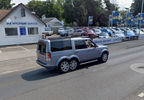
Thread upload1 viewsImage uploaded in new thread
|
|
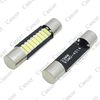
Thread upload15 viewsImage uploaded in thread 132262
|
|

Thread upload5 viewsImage uploaded in thread 175193
|
|
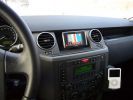
Navi Becker and iPod285 viewsThe Becker Highspeed II was installed in the bin with power connected. Works great, even TMC worked inside the garage right away!
|
|

99 views
|
|

Pulled out344 views
|
|
Thread upload15 viewsImage uploaded in thread 149203
|
|
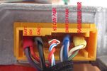
ACC ECU correctly labelled34 views
|
|
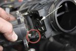
Removing the EGR Butterfly Valve Actuator1521 viewsRemove the 4 TORX screws to remove the actuator. The small black link (circled) connects the actuator drive arm with the butterfly valve spindle (arrowed). The spindle can now be very carefully levered out using a screwdriver inserted beneath the arrowed bit in the photo. A bit scary to do as it takes a fair bit of pressure before the spindle will free itself from the butterfly. Once it starts moving though, it gets easier to pull out.
|
|
Thread upload2 viewsImage uploaded in thread 187641
|
|
167 viewsAcknowledgement to Sniffpetrol.com
|
|

Land Rover Aerial Fin images for both Glass and Metal Roof Disco3 / LR3849 viewsAs well as the two different fins, this pdf also shows the plastic blanking plate for glass roof vehicles where no fin is installed.
The glass roof fin is secured by two security screws from the top into a plastic frangible glue on gasket. The hope is that when struck, the fin will shear off and not crack the glass roof. Re the metal roof design, the fin is secured from underneath via two nuts.
The pdf also shows the various electrical bits related to the antennas. In the UK, the fin would house not only a cell phone antenna but the TV and satellite radio antenna electronics as well; in the States, the Sirius sat radio antenna and a G type cell phone antenna if the phone kit was installed would reside within the fin. The SAT NAV GPS antenna is located within the High Mount Brake Light plastic mounted to the upper rear hatch.
|
|

Fin cell phone aerial drawing190 viewsThe factory aerial for the factory NAV / GPS on my 2005 HSE is within the high mounted stop light lens at the top of the upper hatch door. I do not have the factory installed phone kit, and as such, do not have the fin installed; instead there is just a plastic blanking insert to fill the cell phone aerial wiring hole in the metal portion of the roof; hence this requirement for an "external" cell antenna. For those that do have the fin on their glass roof, the fin is screwed on to a glued on plastic gasket, (sort of), and not bolted thru as per the metal roof 3's.
|
|
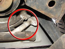
Air Conditioning Pipes (File 1)976 viewsIt\'s the smaller of the 2 pipes that is leaking. Both pipes are encased full length in the foam sleeve. You can see where the support bracket has \'crushed\' the sleeve. The bracket is what holed the small pipe. There is a bracket at each end and one in the middle. You need to remove the suspension reservoir to get to the centre bracket. Be aware that the bolts securing the brackets may be corroded and are likely to shear off on removal!
|
|
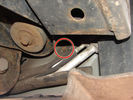
Air Conditioning Pipes186 viewsFront-to-rear aircon HP and LP pipes. The circled bit shows where the bolt securing the support bracket (removed)has sheared off
|
|

38 views
|
|
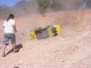
236 viewsOoops!! Tonka lost power and rolled back down onto his side
|
|
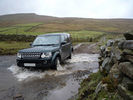
Sleddale96 views
|
|
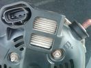
Alternator Plug and B+ terminal910 viewsPictured is the rear of the older Land Rover part # YLE500190 alternator showing the shiny cooling fin of the Regitar VRH2005-142 regulator under.
The first pin in the far left side of the connector is numbered #1 in the LR electrical wiring diagrams and is Battery Voltage Sensing (BVS); the middle pin, #2 receives a Pulse Width Modulated (PWM) signal from the Engine Control Module (ECM), and the right pin, #3 carries a PWM signal back to the ECM. Terminal Pin #2 on the LR wiring diagrams is called Alternator Control or ALT CON; Pin #3 per LR is called Alternator Monitoring or ALT MON.
Pin #1 is similar to what in older designs used to be called A or Batt, but is now called by Denso, S, AS, or Alternator Sensing for this design. Pin #1 also provides power to excite the alternator at startup until the PWM instructions over ride the battery voltage info. Land Rover calls the electronics under the pins a Smart Regulator, ironic, as it has to follow orders from the ECM rather than give the orders - new age thinking I guess. This is different from older design internal regulators that look at just the battery or the electrical buss voltage and then decides itself what to do.
It is almost like we are back to the external regulator designs of old, except that the ECM may decide that instead of telling the alternator to make more power, to load shed, and hence shut down the heated windscreen, seats, or whatever other electrical loads it decides are appropriate. My view is that the "smarts" are in the ECM and that the "regulator" should be regarded if not dumb, then as being a slave to the ECM.
|
|
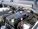
BCI Group 40R Deka 640RMF battery showing vent hose run forward to windshield washer reservoir area 1424 viewsRecessed post "Euro profile" battery to "match" OEM and stock Land Rover bracket; note that the Traxide SC80-LR module is mounted at an angle to allow for the main cable to sit under the cover so cover still closes.
The battery is a nominal 7", (180mm), high, but sits on a 1" battery spacer set under to raise the bottom front end of the battery such that the approx 11", (290 mm), length of the BCI 40R battery rises above the angled plastic nibs at the forward end bottom of the case front; hence sufficient space, (1/4", 5mm) remains at the brake reservoir end.
Also the 40R battery does not have hold down "flanges" on each end; on the sides yes, but not the ends so no additional length is required.
When I had to replace the 40R, this time I installed the shorter, (9.625"), taller, (7.5") Interstate BCI 47 / DIN H5 battery which eliminated the spacer on the bottom and better fit the stock LR tie down bolt lengths. Deka also has a BCI 47 / DIN H5 that would work fine as well.
|
|
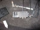
1071 views
|
|

D4 Auxilliary or Second Battery installed in Aux Battery Box214 views
|
|
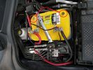
D4 Auxilliary or Second Battery installed in Aux Battery Box, Vents Circled188 views
|
|
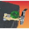
Battery Disconnect Wirthco 20308 Knob Top Post 889 viewsThis is a battery post style disconnect, usually for the negative terminal. There is a hole drilled in the round end off the battery so that flat terminal can be attached as well as the normal battery post terminal. I did not use this hookup arrangement, however I show it for information only.
|
|
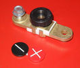
Battery Disconnect side post with + & - caps, top view616 viewsThis disconnect is designed for side post batteries. It can be used on either the + or - terminals. It can also be installed at the "other" end of the battery cable as well. In my install of the Aux battery, I installed this on the negative ground cable where the cable attaches to the body sheet metal. I have never used it but it seemed like a good idea at the time. The main battery hookup is pure stock.
For the hot side of the Aux battery, an Anderson PowerPole was used inline for the cable between the Aux and connecting to the spare bolt hole at the + post of the Main battery cable.
|
|
Woodlands Hotel5 viewsGreen Oval Garage would like to say thank you to the Woodlands Hotel in Leeds for allowing us the use of their beautiful grounds for all our future photos shoots.
Woodlands is one of the finest luxury hotels in Leeds. This boutique hotel is set in beautiful landscaped grounds on the outskirts of Leeds city centre, just 2 minutes drive from junction 27 of the M62 motorway, with 23 individually designed bedrooms and an award winning restaurant. Packed with character, this lovingly restored hotel is only three miles from the vibrant, cosmopolitan city of Leeds with superb nightlife and unrivalled shopping.
Woodlands also offers a stylish and contemporary functions venue for all kinds of social and business events. Our three stunning event spaces are suitable for everything from wedding ceremonies and receptions, to corporate meetings and events. The permanent marquee, attached to the hotel, can accommodate up to 150 for dining and 200 for evening parties and receptions, making it one of the most elegant settings for a wedding venue in the Leeds area.
For more information or to make a booking, please contact us on enquire@woodlandsleeds.com or 0113 2381 488
|
|
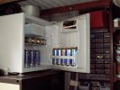
Beer Fridge Partially Filled75 views
|
|
Thread upload6 viewsImage uploaded in thread 137017
|
|
Thread upload117 viewsImage uploaded in thread 69791
|
|

Buckingham Blue D3 Screen Saver201 views49 frame (8 base frame) animated 100x46 pixel image in size cut from the Discovery 3 Accessory Builder screen - modelled after my D3 - running on my phone!
|
|
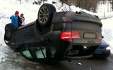
bmw sledge58 views
|
|
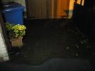
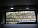
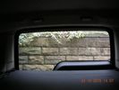
LED light ON - looking out from boot80 views
|
|
LED light OFF - looking out from boot67 views
|
|

LED light ON - looking into boot84 views
|
|

LED light OFF - looking into boot73 views
|
|

Black Deposits to interior of Brake Light Switch2830 viewsThere are two contacts, one on each side of the vertical plunger under the copper metal. The set of normally open contacts on the left side that carries the power for the brake light filaments, (15 amp fuse F15P), is apparently not heavy enough as the contacts deteriorate and generate the black residue.
The set of normally closed contacts on the other side appear to be sized OK. There is not as much current, (5 amp fuse F66P), flowing thru the contacts to the ABS module, however the contacts are likely adversely affected by the black residue produced by the other deteriorating set of contacts.
One presumes/hopes that the newer replacement switch now has contacts heavy enough to carry the brake light power. It would be ideal if the ABS set of contacts were sealed from the brake light contacts to prevent contamination of the normally closed set of contacts.
|
|

Brake Light Switch, Find, Remove, and Install Instructions 7775 viewsThis is a two page doc outlining where to find the brake light switch, how to remove it, and then install the new one.
Note, do not move the brake pedal when removing or installing the switch. Let the brake pedal hang where it wants to. The switch design is actually cunning, and as such is supposed to make the removal and install fool proof. Hence if you think too much about it, you can wreck the new switch.
If you want to inspect the interior of the switch, wait until you have removed the old switch. You can then just unsnap the blue from the white to get it apart. Inside, the switch is quite simple, (no circuit boards), but it will probably show black dust from failing contacts.
I think the reason the switch fails is that the Normally Open, (NO), contacts of the brake light contacts were made too light to carry the current load for make and break of the tail light filaments. I also think the black dust created then fouls the Normally Closed, (NC), second set of contacts for the ABS circuit. As such, the Normally Closed contacts become intermittent in operation and display as a fluctuating open and closed circuit condition to the ABS system when the ABS should be seeing a steady closed circuit. Hopefully the replacement switch contacts are more robust and may be as I recently replaced my switch again just as a matter of maintenance. While in a redesign, ideally the NC contacts should be sealed or at least separated from the NO contacts, when I inspected the removed switch, this time there was no black dust present.
Probably the removed switch will have a Land Rover oval logo moulded into it, the new one, FOMOCO.
|
|
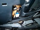
Brake Switch Visible thru Opening4933 viewsThe blue and white bit is the switch; the sort of gold appearing box,(it is really black), you will not see in your 3 as it is a Smooth Talker brand amplifier for my Blackberry phone antenna. This install is detailed in the SmoothTalker phone antenna section of my gallery.
One way to remove and install the switch is to lower the "horizontal" panel above the brake pedal as shown where the flashlight head is located. To actually remove the switch, you slide your hand thru the gap and rotate the switch clockwise 1/4 turn while watching thru the rectangular opening. Installation of the new switch is the reverse of above - 1/4 turn counterclockwise.
Before you remove the switch, note its orientation - horizontal with electrical wires to the left. That is the way it should look after replacement as well.
The second time I replaced the switch, I did it all thru the rectangular opening and did not remove the horizontal panel - that is experience helping out.
The knee kick you have to remove regardless. It is sort of hinged at the bottom so you just pull at the top and sort of rotate the knee panel and then pull upwards for two plastic "fingers" to clear the slots they reside in.
|
|

Black Deposits on Brake Light Switch Plunger2730 viewsThis jpg I got off another forum and is typical of what one will see when one opens up the removed brake light switch. The black powder is residue from arcing of one of the pair of contacts within.
Hopefully the newer switches with the FOMOCO logo moulded into the plastic are improved from the Land Rover logo marked early units, however I doubt it.
The Ford part number is SW-6572 and/or 7E5Z-13480-A as used on the 2006 to 2009 Ford Fusion's and Mercury Milan's; the Land Rover part number is XKB500110. Cost of switch could be about twenty five dollars. A previous LR part number for the switch was XKB500030, so hopefully the newer LR part number, XKB500110, reflects some improvement in reliability.
It is possible that the new switches are better as I installed a replacement 72,000 km, (45,000 miles) later, at 195,000 km (121,000 miles). When I took the removed switch apart to inspect, it was clean inside. There was no black dust - the switch looked like new, hence they must be improved now.
|
|
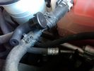
Breather line with factory cap cut off.2275 viewsIf you expand the jpg by clicking on it, in the bottom right corner if you look closely, one can see the black plastic factory vent tubing with the OEM cap cut off.
Note the tubing is cut at a 45 degree angle facing to the rear. Also shown in the top right is the cut off portion sitting on the coolant water hose and on the top left also sitting on the coolant hose, the new to be installed Gore manufactured replacement breather cap.
|
|
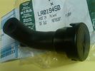
Breather Cap part # LR0194501509 viewsThis is the replacement breather cap as manufactured by the Gore Tex people, (Gore), for the engine compartment end of the front differential breather line.
You can with some difficulty, both blow and suck thru the breather filter material. The Gore Tex filter material has what are called hydrophobic and oleophobic properties. This means the filter material keeps oil in and water out, while at the same time, allowing air pressure to slowly equalize, (air permeable). Additionally, the transfer of dust, salt, and road debris is inhibited.
|
|
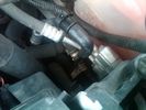
Breather Cap Installed1970 viewsThe black L shaped tube is is the Gore manufactured, (the Gore-Tex people), LR4 Breather Valve installed in an LR3. Naturally the installation looks similar to what one sees on an LR4 or RRS as the Gore breather valve is now OEM for new production.
The part number of this upgraded front differential breather valve is LR019450 and costs about thirty dollars.
|
|
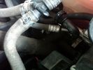
New Breather Cap installed.1674 viewsThis shows the new Gore brand angled breather cap installed. The cap points rearward to the firewall. Also shown is the cut off piece.
The new Gore breather cap is what one now sees on the LR4 and RR Sport.
|
|

109 views
|
|

338 views
|
|

Thread upload25 viewsImage uploaded in new thread
|
|
Thread upload0 viewsImage uploaded in thread 177818
|
|

89 views
|
|
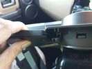
Edge of H Trim filed to allow screen to rest flush on front5 views
|
|
D3 Side Step Repairs161 viewsI then drilled out the holes in the step edge to 5.5mm to accomodat my larger rivets.
|
|
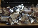
LEDs13 viewsBig box of LEDs from HIDS4U
|
|
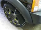
Snow Chains Installed - Land Rover LR3HSE94 viewsSnow Chains that seem to fit a Land Rover LR3HSE
|
|

Thread upload5 viewsImage uploaded in thread 157984
|
|
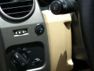
Long Ranger auxilairy fuel tank pump switch and tank gauge307 viewsFitted to the right of the air vent thumbwheel, the neat combination switch and gauge take sup no room at all. Switch locks on or off, but no pump running warning lamp! Contents of the tank are indicated by 5 LEDS, 4 green and 1 red for full, 3/4, 1/2, 1/4 and empty. Pump transfer rate of just 2 litres p/min is disappointing. I transfer on the move when main tank is at 1/4.
|
|
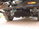
LongRanger auxiliary fuel tank356 viewsThe LR fuel tank imported from ARB in Australia with its 115 litre capacity has more than doubled the range of the car. This is important in the desert where fuel consumption increases at times to 10mpg or less. On a cruise on highways, the car now has a range approaching 850 miles. The tank fits neatly, has not affected handling in a detectable way apart from over speed humps, when a little more bounce from the rear suspension is detected! Suspension copes with the additonal loads without any problem.
|
|
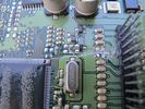
central junction box - resistors badly pulled 178 viewscentral junction box - two resistors pulled, PCB scratched
|
|
35 views
|
|

TDV8 to Date248 views2007 (57) TDV8 HSE
Mods:
BAS mapped.. oh yeah..
Colour coordinated lower sills,Java handles, supercharger vents and grill
Hawke smoked repeaters
Halo style HD LED rings in headlights
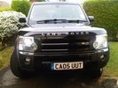
22" supercharger style diamond cut alloys
2011 LED rear lights
|
|
16 views
|
|
13 views
|
|
Thread upload11 viewsImage uploaded in thread 136275
|
|

Controller 2130 viewsI find that the controller is easier to use when angled forward
|
|
CounterAct Power supply mounted under brake lines.191 viewsThis top view shows where I located the power supply. It is attached with 3M sticky to the black plastic surface that is located under the brake lines.
When the system is operating properly, the red LED pulses about twice per second.
Some users claim they can hear a very slight hum or whine coming from the unit. My unit seems silent.
|
|
230 views
|
|
189 views
|
|
162 views
|
|
225 views
|
|
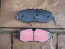
178 views
|
|
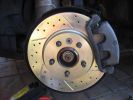
186 views
|
|
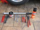
tools needed 197 views
|
|
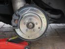
Rear disk 213 views
|
|
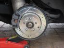
rear disk174 views
|
|
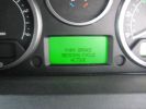
EPB bedding in display 369 views
|
|

Cubby fridge installed in 10 minutes44 views
|
|

Installation completed67 views
|
|

I think reverse gear is called for. Ooh my sump guard was still straight here!95 views
|
|
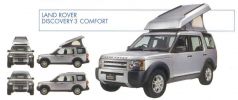
Land Rover Discovery 3 'Comfort' - Detailed views405 viewsCopied from Land Rover Magazine Number 40 (Japanese edition)
|
|
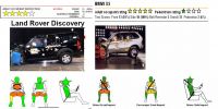
D3 vs X5 in NCAP crash test411 views Looks that D3 was as close as it can be to get 5 stars but falled JUST below the 5 star limit.
|
|
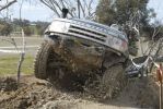
242 views
|
|
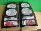
Thread upload5 viewsImage uploaded in new thread
|
|
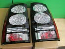
Thread upload5 viewsImage uploaded in new thread
|
|
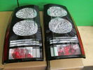
Thread upload5 viewsImage uploaded in new thread
|
|

D4 Headlight (Xenon) LEDS (Angel Lights)98 viewsD4 Headlight (Xenon) LEDS (Angel Lights)
|
|

D4 Headlight (Halogen) no LEDS (Angel Lights)74 viewsD4 Headlight (Halogen) no LEDS (Angel Lights)
|
|
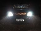
D4 hid kit installed and outside in the dark 6000k conversion.284 views
|
|
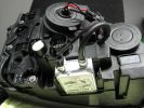
D4 hid installed in light ready to go213 views
|
|
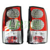
Thread upload3 viewsImage uploaded in new thread
|
|
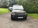
Thread upload27 viewsImage uploaded in thread 174656
|
|

Thread upload0 viewsImage uploaded in thread 172895
|
|

Thread upload0 viewsImage uploaded in thread 172895
|
|
Thread upload0 viewsImage uploaded in thread 172895
|
|

Thread upload0 viewsImage uploaded in thread 172895
|
|
Thread upload0 viewsImage uploaded in thread 172895
|
|
Lamp mounting details133 viewsTwo holes have to be drilled into the frame to fasten the brackets
|
|
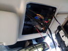
Wires installed for roof console122 views
|
|
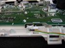
177 views
|
|
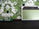
179 views
|
|
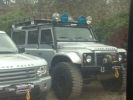
74 views
|
|

Thread upload1 viewsImage uploaded in thread 172661
|
|

Deka Battery Dimension Data613 viewsThe battery size that I installed for my auxiliary was a BCI 40R battery as it was for me the easiest to fit and was also a cranking battery. The case profile was such that no tie down fins were located on either bottom end, (sides yes), and length wise, it was only about 11" (290 mm) long. As such, I did not have to grind the nibs at the front bottom of the plastic surround.
I did however raise the bottom of the battery above the angled nibs as I set the battery on a 1" (25mm) high plastic spacer. The total height, (battery plus spacer), was about 8" (200mm) so the battery top still fit under the Land Rover factory cover.
For the Aux battery, when I replaced the 40R, I installed an Interstate BCI 47 which is similar in size to a DIN H5. I was therefore able to eliminate the vertical spacer as the Group 47/H5 is the same height as the DIN H7/H8 stock LR spec starting battery. As such, the standard battery tie down bolts can be used without modification. The Group 47 battery is 9 11/16" long x 6 7/8" wide x 7 1/2" (190mm) high.
|
|

Thread upload11 viewsImage uploaded in new thread
|
|
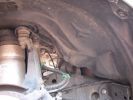
pull out the 3 clips circled in red294 views
|
|
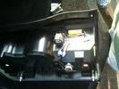
196 viewslocating of resistor to rear of D4 led lights and scotch blocks but theres loads of room so the choice is yours
|
|

256 viewspulled off the factory plastic and found 2 6inch cracks in the drivers side top in front of head light
|
|

Headlight mod and D4 grill mod62 viewsFirst tackle of mods to my D3, First attempt was the D4 grill, then the de-orange of the headlands, Also installed LED sidelights and indicators
|
|
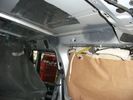
72 viewsFailed area before plating
|
|

Main secondary gear repair bush482 viewsPDF file of engineering drawing of bush turned up to repair the main secondary gear in the EPB gearbox.
Old gear has to be drilled out accurately to the external diameter of the bushing shaft.
|
|

New LED DRLs117 views
|
|

68 views
|
|
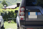
66 views
|
|

68 views
|
|

UHF Radio installed20 views
|
|
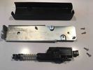
Thread upload2 viewsImage uploaded in thread 187641
|
|

Dom Practices the 'failed hill acent' procedure - 10fc style332 views
|
|

Driving 101 - a humourous PowerPoint Presentation file144 viewsItalian and humourous. Turn the sound on and have a quiet chuckle at the show. Only let the children watch if they are able to accept animated violence (some life forms were injured or killed in the making of this animation!!).
|
|
D2 in Fife 201114 viewsShe was called Fi
|
|

led bulbs113 views
|
|

Spyder LEDs136 views
|
|

Spyder LEDs143 views
|
|
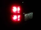
Spyder LEDs175 views
|
|
Spyder LEDs side view146 views
|
|
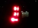
Spyder LEDs with fog lamps on163 views
|
|
Spyder LEDs with brake (Sorry for the blurr)162 views
|
|
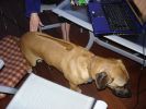
That's why they're called Ridgebacks343 views
|
|
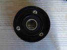
aux belt roller re-assembled49 views
|
|
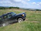
10forcash crossaxled, but he made it402 views
|
|
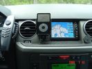
I-Pod installed into my Disco 3451 views I-pod video and Geosat2c installed. No visible damage to the deskboard, no holes etc.
|
|
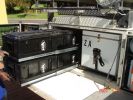
Drawers pulled out203 views
|
|
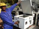
Fridge pulled out & open ( thats my mate, Caiphus)213 views
|
|
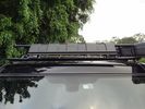
Wind Deflector for Rack14 viewsRecognise this part? Its the lower front recovery point cover. Installed upside down to silence the wind "drone" on the roof rack - works a treat!
|
|
new conquest on the way to get the LR wheels installed203 views
|
|
BAS FBH Controller Installed 188 views
|
|

Kids from Ruacana school in Namibia147 viewsThe kids at some South African schools donated libraries and stationery which we were handing out. THe also filled a book with pictures of themselves and messages to the kids of the schools Kingsley\'s mission were to visit. In return the kids from the destination schools wrote messages back to the SA kids. Very Cool!
|
|
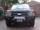
ARB333 viewsARB Bullbar and Warn tabor winch, with detachable tow ball(not installed).
|
|
Wera-Facom Flex-HP Vortex-HP-Facom Sealed Pear59 views
|
|
Drilled 56 mm hole to the front bumber306 views
|
|
Drilled 56 mm hole to the front bumber300 views
|
|
Smoked stripe on the windscreen438 views Installed 5 % foil into windscreen to hide the rear mirror tft lcd display a bit from the possible thiefs.
|
|
Rear mirror with LCD TFT display installed459 views
|
|
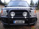
Driving lights installed432 viewsinstalled with Defender styled alu parts
|
|
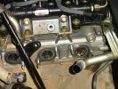
Dead engine135 viewsExhaust ports showing where leaked coolant has gone into the manifold and filled the turbo
|
|
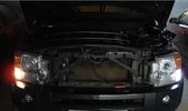
LED sidelights56 views
|
|
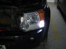
LED sidelights60 views
|
|
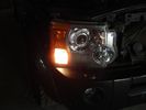
LED sidelights55 views
|
|

59 viewsD4 LEd lights
|
|
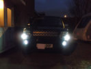
Day running lights & led side light upgrade284 views
|
|
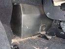
Right side floor-level view of water tank.150 viewsShows tie-down bolt (one of 2 securing the tank). Also note small void on side, which permits tank area to dry out if accidentally overfilled.
|
|
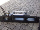
Hidden winch mount with winch in place122 viewsHydraulic hoses are now installed. Note notch for hydraulic:electric solenoid to fit in mount.
|
|
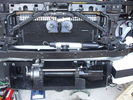
Front bumper view of semi-installed winch118 viewsNote the left-side (looking forward) bracket holding the white windscreen washer bottle.
|
|
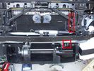
Installed winch with hydraulic hoses175 viewsThe hydraulic hoses are stiff, so I had to run them up the side of the radiator (can just see inside red boxes) to near the top of the radiator, then back down inside the engine compartment, then underneath the engine (behind the radiator) to the D4's power steering rack, where the hoses become metal. This hose routing may not be possible if the fuel-burning heater is in place (we don't have those in Aust and the space allowed room for my hands to bend and run the hoses without kinking).
|
|
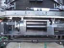
Close-up front view of partially-installed winch120 viewsNote that the sheet-metal flange just above the winch had to be notched to allow winch controller to be actuated. Also this same bracket had to be bent upwards to allow the winch hydraulic:electic solenoid to fit without rubbing. The nut on the upper-left bolt (the one with a very faint circle around it) stripped on re-installation, so the tray and winch pulling load is held only by the threads on 7 bolts....
|
|
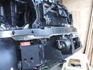
Front-right view (looking forward) of partially installed winch and mount122 viewsThe closest bracket, with three rubber grommets, is the air bag sensor. Before beginning any of this work, be sure to disconnect battery and discharge any remaining electrical power. I didn't want to accidently drop this assembly and cause the airbags to deploy.
|
|
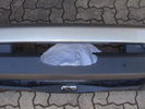
Front bumper with cutout for winch rope entry115 viewsBumper was initially cut "too small" with a low speed hand-held jig saw. It was then progressively filed to about the right size. Finally a very sharp box cutter was used to provide a smooth edge to the cut. This cutout is hidden behind the licence plate.
|
|
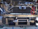
Installed winch with electrical solenoid connections158 viewsI routed the electrical supply (2 small wires) up the side of the radiator. You can see the unconnected wires inside the red boxes. I ended up connecting them on the radiator diagonal strut with cable ties. They are out of the way for any deep water transits there.
|
|
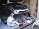
Installed winch, with bumper partially re-installed202 viewsPutting the D4 back together. Shows the tools and owner lying about.
|
|
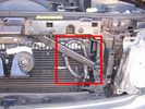
Installed winch electrical wires146 viewsWires which only power the solenoid are inside spiral wrap. They are also connected inside the wrap at the high point of the loop. Cable tied into place to prevent vibration rubbing.
|
|
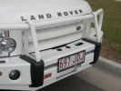
Winch as installed176 viewsLicence plate is held on by winch cable and 4 metal pins which fit into modified bumper body. Winch rope is green
|
|
Interior LEDs19 views
|
|
Interior LEDs15 views
|
|
271 views
|
|
DVD Installed175 views
|
|
Rear LED lights (2)40 views
|
|
Rear LED lights38 views
|
|
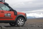
calendar entry 2009528 viewsHigh in the Iceland Interior June 2008 - F88 to Askjar Volcanoe - The mountain is called the "Queen of the Mountains - Herðubreið" Car is G4 Challenge Event Car from 2006 - Team Germany / Spain - Stage 3/4 Bolivia
|
|
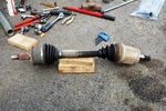
FNS Drive shaft with failed boots94 views
|
|
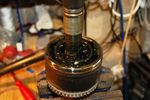
Reassembled with new grease92 views
|
|

Part assembled100 views
|
|
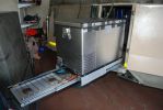
built fridge slider in front door (as opposed to rear) which makes fridge available at the kitchen. Also added drawer for gas stove - stows easily under the fridge when not in use. can be used independantly of fridge, ie. whether fridge is pulled in or ou113 views
|
|
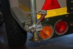
fitted stronger rear strut holders. not a great mod. the holes i drillled for the "R" clips are the best mod, as they stop the legs from sliding up under pressure. requires bracing inside to stop chassis bending100 views
|
|
139 viewsbracket installed into existing mounting holes for coolant reservoir
|
|
120 viewsThe plate installed on top of the bracket
|
|

Oppo10 views
|
|

17 views
|
|

Thread upload3 viewsImage uploaded in thread 146438
|
|
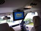
10.2" DVD player installed519 views
|
|

Rosen 7500s installed123 viewsrosen 7500
|
|
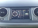
The Tablet Installed 15 views
|
|

2009 LED164 views
|
|

119 views
|
|

2 views
|
|
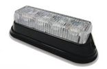
EVS Gen. 3 LED flasher63 views
|
|
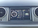
The Tablet Installed 26 views
|
|

The smell of Adreneline307 views
|
|

Fan Connector - wires pulled out38 views
|
|
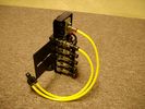
FASKIT on end view 859 viewsEnd and rear view of the FASKIT. Yellow lines are as shipped for hooking to the air supply; one line to valve/filler and other is to gauge. I will modify the arrangement to delete one of the yellow lines such that gauge line plugs into where the second yellow line is right now,(will be only one yellow tube), and then the air source line will plug into the port controlled by the valve, (hidden in this view but visible in other view). When white valve is in the ON position, gauge will read air source pressure, and be available to supply air to any of the selected four air springs. When valve is closed, the gauge will show individual air pressure in each of the air springs when a jumper is run between the gauge Schrader valve and the appropriate air spring Schrader valve.
|
|
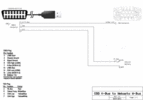
63 viewsOBD2 adapter to FBH wiring diagram, corrected and labelled for plug view.
|
|
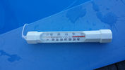
water temp5 viewsjust filled pool and checked water temp
|
|
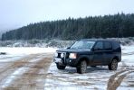
Calendar Entry329 views
|
|
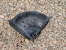
195 views
|
|

196 views
|
|

Thread upload13 viewsImage uploaded in thread 139920
|
|

Thread upload7 viewsImage uploaded in new thread
|
|

Thread upload9 viewsImage uploaded in thread 139920
|
|

Fluid, Filter/Pan Combo removal and install5947 viewsThese are the LR instructions re removal and install of the plastic pan/filter combo for the ZF 6HP26X transmission on the 4.4L petrol V8 LR3.
The instructions tend to ignore the reason you have to lift the right hand side of the engine about 40 mm. This is because of a frame cross member that interferes with dropping down of the plastic pan. The real problem is a vertical "oil filter spout" that rises out of the filter/pan combo up into the transmission. The spout is the suction pipe for filtered transmission oil back up into the tranny.
On the metal pan versions, the filter is separate from the pan, hence the filter remains with the tranny when the metal pan is dropped. The filter is then removed or installed independent of the metal pan, hence with the metal pan, there is no need to lift the engine.
If one is removing the plastic pan so as to install the metal pan, then some do not lift the engine but just drop the plastic pan enough to gain access to saw off the vertical plastic spout - it is a one time procedure.
Be aware however that the metal pan uses a flat gasket and the plastic pan uses a O ring like perimeter gasket that sits in a half round groove in the tranny casing. Also the metal pan uses 21 shorter torx M6x22.5 metric cap screws for the perimeter bolts. The plastic pan uses longer M6x28.5 torx metric cap screws.
|
|

Thread upload1 viewsImage uploaded in thread 198799
|
|

Fogs & LEDs Wiring - Pic 181 views
|
|

Fogs & LEDs Wiring - Pic 262 views
|
|

Fogs & LEDs Wiring - Pic 360 views
|
|

Fogs & LEDs Wiring - Pic 456 views
|
|

Fogs & LEDs Wiring - Pic 555 views
|
|

Exploded Parts view calling up 6R60/80 and 6HP26/28 variations3094 viewsThis single page jpg exploded parts view indicates some commonality between the Ford and ZF versions of the early and later six speed units. Technically this sheet is for the RWD units as there are variations between plain RWD units, 4WD, and AWD. The transmission in the LR3 is called by ZF to be a 6HP26X and by LR in some publications, the 6HP26
|
|
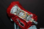
Ford 6R60 six speed cutaway showing torque converter.2188 viewsThis is a cutaway of the Ford 6R60 six speed which is a Ford license built version similar to our ZF 6HP26 six speed speced on early 3's.
The newer 3's and 4's have the ZF 6HP28. The Ford version is called the 6R80 and variations of it are used on the Raptor. As such, the Raptor metal pan can be installed on the 3's tranny but the deeper Ford Raptor pan does not have a drain plug.
|
|
LED120 views
|
|
LED105 views
|
|
LED sidelights182 viewsI wish I\'d done a before pici - the LEDs are brighter, and much better match to the headlights.
|
|

Front Side Light New LED Bulb.437 views
|
|
LED Mirror Covers64 viewsLED Indicators & Welcome Lights in the Mirrors
|
|

disco3.co.uk instructions for removing wheelarches (with photos)641 viewsCourtesy of a senior member of the site - detailed instructs for removing the wheelarch trims and front bumper - use in conjunction with the other 2 documents
|
|
Thread upload8 viewsImage uploaded in thread 130828
|
|
Thread upload6 viewsImage uploaded in thread 136532
|
|
Thread upload7 viewsImage uploaded in thread 130828
|
|
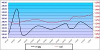
MS Excel chart of fuel usage in TDV6 first 3 months of ownership200 viewsReason for distortion at beginning is not known - average so far is 11.55l/100k (25.09mpg) for the 6 199k travelled. The fuel usage 'bumps' correspond with the city driving although they did mirror the cost for a while! A copy of the spreadsheet (105kb) that shows MPG and l/100k (but not miles) is available for the asking - just PM me.
|
|
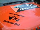
Tigger - Team DurtyDisco (The DoubleD's) for the Mac4x4 201354 views
|
|

Thread upload7 viewsImage uploaded in thread 205962
|
|

Fix stiff gear selector or jumping out of drive into neutral32 viewsThis is a document culled from a topic about a simple fix to teh gearbox selector lever that fixes a problem with jumping out of drive into neutral.
I made the document to give to my local independent and thought it might be useful for others.
Thanks to disco_mikey, EdF and Robbie from the original post whose information and photos made this possible (I take no credit for anything here apart from errors).
|
|

Fix stiff gear selector or jumping out of drive into neutral17 viewsUpdated 19 Dec 2012
This is a document culled from a topic about a simple fix to the gearbox selector lever that fixes a problem with jumping out of drive into neutral.
I made the document to give to my local independent and thought it might be useful for others.
Thanks to disco_mikey, EdF and Robbie from the original post whose information and photos made this possible (I take no credit for anything here apart from errors).
Updated after I did this fix on my own car.
|
|

Thread upload18 viewsImage uploaded in thread 169555
|
|
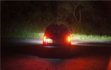
Thread upload8 viewsImage uploaded in thread 143957
|
|
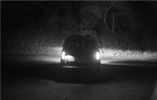
Thread upload11 viewsImage uploaded in thread 143957
|
|

Thread upload1 viewsImage uploaded in thread 157814
|
|

Thread upload1 viewsImage uploaded in thread 157814
|
|

map light134 views
|
|

High power led128 views
|
|
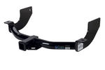
Curt Manufacturing brand hitch, assembled but not installed.282 viewsThe Curt Manufacturing hitch is an alternate to the Land Rover removable "plow" hitch. Once bolted in place, the Curt hitch is always there.
The Curt part number is 13456. It is a Class III hitch with a 2" square receiver and designed for a maximum 600 pound tongue weight.
The hitch hangs below the rear bumper but does not stick out past the bumper; also the "donut" spare tyre can still be installed / removed; am not so certain about a full sized fully inflated spare.
|
|
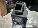
Rhino Tow Loop Hitch263 viewsThis is a receiver end view of the Rhino Hitch that ties to the factory tow loop. In addition to improved strength, it does not reduce ground clearance as does the factory style when installed.
Land Rover in early advertising videos when the 3 first came out showed the D3 hanging from a crane via the frame. The intent was to show how strong the frame is and by inference, the rear tow loop, specifically noted as being good for 6 tonne. The video ends before anything dropped or was lowered back to the ground, so one of course does not know for certain. The Rhino Hitch design however picks up on the apparent evidence of strength and certainly the additional clearance.
|
|

Thread upload0 viewsImage uploaded in thread 204567
|
|

Thread upload1 viewsImage uploaded in thread 204567
|
|
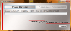
iidtool error after failed firmware update39 views
|
|

Thread upload10 viewsImage uploaded in new thread
|
|
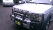
front of D3 with DS2 installed70 viewsPair of Rigid DS2
|
|

Side protection bars installed.48 views
|
|

Before side protection bars were installed.39 views
|
|

Mud flaps installed.39 views
|
|

D4 battery tray installed34 views
|
|

Traxide SC80-12, D4 tray and Optima D34 installed41 views
|
|

Close up - Solenoid14 viewsA close up of the solenoid which is installed close to the auxiliary battery bay.
|
|

New switch18 viewsNearly 5 years ago, I fiddled with some push-buttons, until one day I came across those marine Contura rocker switches :)
The remote control is the switch just behind the EPB.
|
|
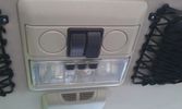
The on/off switches of the multimedia headrests14 viewsThese switches were installed to power on/off the previously installed gamecube and the screens attached to it.
When I removed the gamecube and lately the screens as well, I was clever enough (surprised as well) to leave the switches and all the wiring that I had running around.
They came in handy when I installed the multimedia headrests and are now adding an extra power on/off control of the screens.
|
|
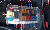
Fuse box in the rear12 viewsI installed the fuse box in the rear. Since I do have a 5-seater, there's plenty of space in the booth beneath the 2nd cover, which rests behind the second row seats.
|
|
Outside connection to the compressor14 viewsFrom the compressor which is in the booth, the air hose runs to the back of the car.
I was able to install the connector in the space of the second trailer plug (which wasn't installed anyway).
|
|

President Johnson II in its current position16 viewsThis CB was installed some years ago and still is at the same location.
However, I'm planning to move it to the head unit area.
As such, I'm looking around to replace my low end head unit with a single DIN radio and the CB on top of it.
|
|

60 viewsFinal setup, everything in place after about one full day of work, which included removing quite some bits I had installed before.
|
|

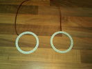
An extra twist on running lights28 viewsAdded those nice 120mm LED rings on the covers of the roofrack lights and have them connected to my roofrack lights switch, as I wanted to control the LED manually as well (I don't believe this is 'road-legal', hence why I opted for the manual solution).
|
|

Cyc.202 viewsOne of My dogs. Cyclops. Yes he has two eyes. He is called Cyclops because He used to walk backwards, sometimes, when he was a pup & He is a monster.
|
|

Rare D3 led lights69 views
|
|

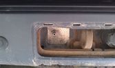
Emergency tailgate opener35 viewsDrilled a little hole for the string tied to the talgate cable.
|
|
Led location - red led on left A pillar 25 views
|
|
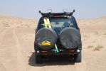
View the Nissans saw105 viewsRecovery strap pre-shackled to the rear recovery eye and secured with a bungey strap to the rear door ladder saves a lot of time when running against the clock - and having to recover a bogged in Nissan!
|
|

led install101 views
|
|
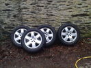
set of four land rover 19" 6 spoke alloys with wrangler MTR's as per G4 spec29 viewsFor sale the set of four tyres and wheels . tyres are new having only traveled 2000 miles
|
|
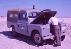
End of the line at Ras Al Khaimar65 viewsI am led to believe that this example was left overnight on the beach broken down - by morning the natives had stripped every last piece of usefull equipment out of it, engine and all and dragged it across the creek back to their village
|
|
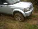
Oops17 viewsPulled free at last!
|
|

Led conversion kit52 views
|
|

DRL Loom Installed12 views
|
|
Led right hid left fog light 45 views
|
|

LED tube 118 views
|
|

LED tube 219 views
|
|

Hids rear LEDs.. They rock... 43 views
|
|
A troubled sky13 views
|
|
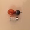
D4 indicator bulbs led 36 views
|
|
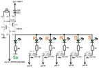
Thread upload6 viewsImage uploaded in thread 168271
|
|
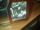
HIDS LED76 views
|
|
NEW LED SIDE LIGHTS AND INDICATORS (headlight MOD complete baby)88 views
|
|

Red Interior LED\'s Fitted95 views
|
|
LED\'s for Front Fogs80 views
|
|
D4 Lights Installed121 views
|
|
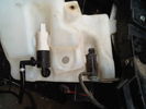
Hole Drilled for New Pump115 views
|
|
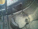
Hole Drilled for Sensor109 views
|
|
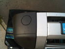
Hole Marked on Bumper Only to be Drilled & Cut118 views
|
|
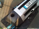
Template on Rear of Bumper Drilled119 views
|
|
First Hole Drilled & Bezel Fitted117 views
|
|

Hole Drilled/Cable Pulled Through118 views
|
|

LED's Fitted to Fogs122 views
|
|

LED's 125 views
|
|

SUN-LR_SET195 viewsThis pic has been taken in Italy,it was almost dark,but the sun was still illuminating the bottom of this high altitude clouds called cirrus
a perfect atmospher
|
|

273 viewsThis pic has been taken in Italy,it was almost dark,but the sun was still illuminating the bottom of this high altitude clouds called cirrus
a perfect atmosphere
Piadina is the man!
|
|

2035 viewsEverything pulled to bit\'s in order to get cables in for PC Screen etc.
Note the panel with USB and LAN connectors on, this replaces the LR panel with the ash tray in.
|
|
Ground anchor assembled ready for use.296 views
|
|
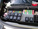
Picture of the engine compartment fuse panel5751 viewsEngine compartment fuse panel located near the battery. This is where F3E, (5 amp), F26E, (20 amp), Fuseable link 10E, (60 amp) and Relay 7E, the now upgraded 70 amp air compressor motor relay, part number YWB500220, (E is for Engine compartment fuse box), are all located. Fuse F35P, (5 amp), is inside the Passenger compartment behind the lower glove box door.
To keep the suspension from going down to the stops when driving, (or parked), it appears that it is only really necessary to remove F26E to depower the exhaust valve and generally keep all the valve block solenoid valves in a closed position trapping whatever air is within the air springs. F3E gets its power thru F26E, so when F26E is removed, the F3E circuit is automatically de-powered. F35P is more interesting in that battery power goes thru the ignition switch and F35P and then into the air suspension control unit. Apparently however, if F26E is removed, removing the F35P is not needed even when the engine is running.
With all fuses still in, if you have a problem, in practice, ideally, the compressor still works and will raise the 3 to an appropriate height. If so, one can then shut the engine off and allow the computers to go to sleep and then you remove the fuse(s). In actual practice, it seems that one need only pull the F26E fuse and can do so with the engine running. All the same, one might consider that the 3 is first a mobile computer, and secondly a 4x4. Computers prefer to go to sleep before the plug is pulled on them, however given that F26E circuit is always alive, then the computer never sleeps. With the fuse(s) pulled, and if you are still up, you can now be a 4x4 instead of a low rider. The whole purpose of the fuse pulling exercise is to depower the one and only system exhaust valve that is physically located within the compressor unit, (to keep it from opening), and secondarily to keep closed the four air spring solenoids within the block valves. This also shuts the air compressor down and stops the air compressor from making air even if the compressor is still good. That is why you initially need the fuse(s) in to allow the compressor to make air if it can.
|
|

Switch is blue colour thing thru the rectangular opening.3149 viewsThe blue coloured plastic bit thru the rectangular opening is the brake light switch. The fist time, I found it easier remove the switch by dropping the horizontal plastic panel, (two screws), and then slipping my hand in and rotating the switch clockwise 1/4 turn. The second time, I was able to remove the switch thru the rectangular opening and did not need to remove the horizontal lower panel. Obviously, I had to remove the sloping knee pad panel, (note sort of hinged at the bottom so pull back from the top.)
Regardless, do not touch the brake pedal - just let it sit where it wants to. One has to first remove the angled knee pad panel that sits under the steering wheel. It can be pulled from the top corner at the door side. Pulling releases a pair of those U shaped metal clips that LR loves so dearly. You have to pull quite hard. The bottom is held by a couple of plastic fingers in a couple of slots so you pull at the top till the two clips release and then rotate the panel and pull upwards a bit.
To remove the switch, you rotate it clockwise and pull outwards. Rotating the switch clockwise automatically retracts the plunger back into the switch body away from the brake pedal arm.
Similarly when you install the new switch, the required 1/4 turn anti clockwise rotation action releases the plunger so it lays up against the brake pedal arm and at the same time, secures the switch in place.
To remove the electrical wires, the switch will drop below the horizontal pad and hang from the wires so unclipping the electrical connector plug is fairly easy to do.
|
|

top left hand side fitted66 viewsto show how its angled to fit in with the mouldings
|
|

first Headrest installed 62 viewswork in progress
|
|
LED Sidelight Land rover92 views
|
|
LED Sidelight Land rover 1101 views
|
|
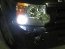
led sidelight or DLR86 views
|
|

A pillar mount installed166 views
|
|

Drilled first, then used cut off wheel on Dremel to "join the dots", then painted.151 views
|
|

Amber leds on rear uprights73 views
|
|
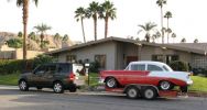
Towing my 56 Chevy263 viewsI towed my Classic Chevy about 650 miles from Palm Springs to Reno, including over the Sierra Nevada mountain pass (7,085 feet (2160 meters)) and the LR3 pulled very well.
|
|
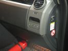
461 viewsFirst step in the journey, installed USB ports.
At the time I installed these, the goal was to use them in combination with the car-computer that resided in the back.
In the meanwhile, I dismantled the car-computer and nearly everything that was connected to it (touchscreen front, Wifi, DVB-T ...).
I kept the USB outlets in the front and turned them into charger for the appliances missus brings with her when we're on holiday. Mainly her iPod and smartphone ...
|
|

471 views@ home, we have 2 remote controlled garage doors. So I installed the remote controller in the car, added 2 buttons and off we go. Lucky me the controller worked at 12V anyway :D
I'll add a LED onto that one, so I'm sure it works when I press :)
|
|
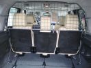
Paddock dog guard view from rear283 viewsInstalled; can see the mounting points
|
|
One happy customer - Artù320 viewsYes, whilst I was fitting everything, he was going mad as he loves to be in the car. He\'s actually had a failed entry into the Disco as it\'s too high for him!!
|
|
230 viewsLED\'s instead of ordinary bulbs, brake applied
|
|

Old Drilled and Grooved disc's14 views
|
|

Side Light - New24 viewsNew replacement LED sidelight from HIDS
|
|

led module55 views
|
|

led module land rover81 views
|
|

led66 views
|
|

led upgrade light82 views
|
|

led interior light77 views
|
|

led63 views
|
|

led64 views
|
|

led boot space light upgrade95 viewsClose up showing how easy the led ultra bright modules fits into original housing
|
|

led boot light70 views
|
|

7 viewsXmas Presy from my so called work mates!
|
|
780 viewsDetailed view of hitch and Anderson plug
|
|
led light to be modified & fitted inside cabin8 views
|
|

suspension 47 viewssuspension will raise when system cooled
|
|
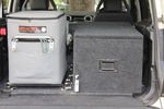
54 viewsengel fridge and cargo drawer rear of the D3.
Base board is MDF, think this may be called ply elsewhere covered with marin carpet on both sides and screwed through the 4x tie down holes with M10 bolts
|
|
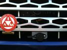
Cabled winch control connector112 viewsAdditional angle bracket made for connector in aluminium attached to red grill. Additional in-line connector between this and the solenoids to allow rad grill to be removed when required.
|
|
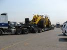
Cat front end loader144 views100 Ton low bed pulled by a Volvo FM 16 610 hp TT.
|
|
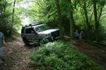
Jason getting x-axled for first time106 views
|
|

Newly installed Freelander2 headrest monitor9 views
|
|
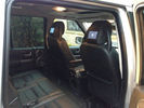
New Rear Seat Entertianment System newly installed15 views
|
|
63 viewsOff Sledgeing
|
|

LED Voltage display44 views
|
|

LED Voltage display31 views
|
|

LED Voltage display28 views
|
|

LED Voltage display28 views
|
|
| 1178 files on 3 page(s) |
 |
1 |  |
 |
|