| Search results - "moving" |

0000 LR Bluetooth dealer Kit install instructions1583 viewsThis 17 page pdf is mostly a series of pictures showing how to install the original Land Rover dealer installed Bluetooth kit for circa 2005 / 2006 three's. Also included are three wiring diagrams sheets related to the pairing code 0000 Bluetooth install.
This pdf is useful if you are now removing the 0000 kit to install the optical 2121 MOST D4 module, an easier install than the 0000 kit ever was.
|
|
Removing the work light251 views
|
|
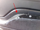
Rimozione pannello dalla sponda - Tailgate panel removing43 viewsPer togliere il pannello moquettato dalla sponda ho fatto leva con un cacciavite abbastanza grosso nel punto indicato, è stato veloce e non ho rovinato niente.
To remove the carpeted panel away from the tailgate I used a big enought screwdriver at the point indicated, it was fast and I have not ruined anything.
|
|

09 Starting to remove the seized brake assembly295 viewsBy this time we\'d poured about 8l of water on the dull-red glowing and burning wheel assembly (too close to 140l of 98 octane petrol). Sudden cooling cracked the disk brake which showed mangled park brake parts. How to remove a brake disk without the right star fitting? First remove the caliper then get a sledge hammer?!!
|
|
1 Removing air bag46 views
|
|
Removing cap (1)80 views
|
|
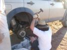
11 Lesson in removing a jammed brake assembly in the Outback378 viewsSpent the next 4 hours doing this to my D3. Gave the photos to Land Rover dealer and they did not think this constituted abuse of the vehicle. I thought that was charitable, but if we hadn\'t done this, the tow back to civilisation would have been even longer.
|
|

12 Half way through removing a jammed disk brake in the Outback296 viewsThis was just before breaking the sledge hammer. Note we luckily carried a spare hammer. Ended up using (or breaking) every tool we had on this little repair job. Bed sheets are a good way of gathering the bits to show for the inevitable warranty claim.
|
|
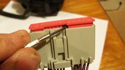
Removing cap (2)75 views
|
|
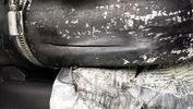
Thread upload131 viewsSplit after removing duck tape. I think the split got longer whilst waiting for new silicone hose's to arrive.
|
|
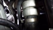
Thread upload128 viewsOriginal LR rubber hose just before removing (turbo end).
|
|
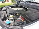
Winch Power upgrade306 viewsUsing 2 warn kits, and removing one of the wires to use on another project. The purpose was to replace the power and ground wire. I used Warn kits, which are 4/0 Welding cable. The original red #4 warped from getting a little too worn. The 2nd
Battery #1 Deka 9A94 AGM Intimidator, Battery #2 Deka 9A47 AGM Intimidator WARN 36080 28" Quick Connect Cable X 2, WARN 26405 Quick Connect Cable 7' X 2, WARN 15901 Black Cable X 1 -- winch control 72" X 1 https://www.facebook.com/DifferentialPartsUS
|
|
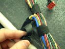
3 Dash loom46 views
|
|
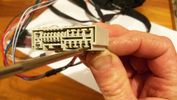
Removing a socket45 views
|
|
Thread upload40 viewsImage uploaded in thread 102519
|
|
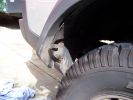
Removing mudflaps292 views
|
|
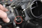
Removing the EGR Butterfly Valve Actuator1522 viewsRemove the 4 TORX screws to remove the actuator. The small black link (circled) connects the actuator drive arm with the butterfly valve spindle (arrowed). The spindle can now be very carefully levered out using a screwdriver inserted beneath the arrowed bit in the photo. A bit scary to do as it takes a fair bit of pressure before the spindle will free itself from the butterfly. Once it starts moving though, it gets easier to pull out.
|
|

ALMA CUSTOM VEHICLE FOR MOVING MASTS OVER DESERT91 views
|
|
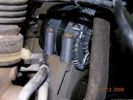
58 viewsOne bolt is visible at the front, but the other two are down the left hand side and best accessed by removing the small plastic guard behind the bumper. I also removed the small metal radiator guard between the bumper and the main sump guard (but that was mostly to retrieve the spanner I dropped!). The only issue with removing the plastic guard is the stupid plastic clips that hold it on may need to be replaced.
|
|

And its moving93 views
|
|
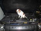
Always start with removing the dog from the engine compartment51 views
|
|

OLD VERSION - Bodsy's Brake Bible v 1.611087 viewsUSE Version 1.6a
Clarified EPB shoe instructions & corrected references to other sections. Added paypal donations information (requested by users of the guide.) Internationalised wheel location references by removing UK based reference to OS/NS, replaced with physical Front Left or Front Right descriptions.
|
|
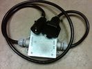
Box Closed with 7 Blade NAS connectors577 viewsBox closed up and ready for use. The box and cable connectors are reasonably weather tight and hence can be submerged for a bit while doing a creek crossing but as with the 3, do not use the creek bed as a parking stall. Similarly, the connector recessed into the bumper will probably remain somewhat dry as long as you keep moving but if you get stopped, well that is another story.
As such, I put a vial of desiccant in the metal box prior to closing it up to reduce corrosion due to moisture build up.
|
|
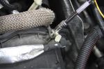
EGR Pipe Bracket 888 viewsRemoving EGR pipe bracket securing bolt
|
|

Brake Light Switch, Find, Remove, and Install Instructions 7778 viewsThis is a two page doc outlining where to find the brake light switch, how to remove it, and then install the new one.
Note, do not move the brake pedal when removing or installing the switch. Let the brake pedal hang where it wants to. The switch design is actually cunning, and as such is supposed to make the removal and install fool proof. Hence if you think too much about it, you can wreck the new switch.
If you want to inspect the interior of the switch, wait until you have removed the old switch. You can then just unsnap the blue from the white to get it apart. Inside, the switch is quite simple, (no circuit boards), but it will probably show black dust from failing contacts.
I think the reason the switch fails is that the Normally Open, (NO), contacts of the brake light contacts were made too light to carry the current load for make and break of the tail light filaments. I also think the black dust created then fouls the Normally Closed, (NC), second set of contacts for the ABS circuit. As such, the Normally Closed contacts become intermittent in operation and display as a fluctuating open and closed circuit condition to the ABS system when the ABS should be seeing a steady closed circuit. Hopefully the replacement switch contacts are more robust and may be as I recently replaced my switch again just as a matter of maintenance. While in a redesign, ideally the NC contacts should be sealed or at least separated from the NO contacts, when I inspected the removed switch, this time there was no black dust present.
Probably the removed switch will have a Land Rover oval logo moulded into it, the new one, FOMOCO.
|
|
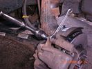
Removing Caliper117 views
|
|
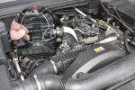
Remove Clip944 viewsRemoving the air box/EGR butterfly housing securing clip
|
|

the road between home and work290 viewsthe day before returning from work, I got stuck here in the middle of the snow storm. The plow didn\'t pass yet and wind was blowing snow everywere. Since then I always carry during winter a survival pack consisting of warm coat,cap, warm, high boots and gloves.
It is no fun recovering a car stuck in the snow and sliding down from the road when moving in nothing more than a business outfit (no gloves, city shoes, no coat) with a snowy wind blowing 100km/h..... .
|
|

27 viewsShort clip of turbo actuator rod moving after key turned to position2/3
|
|
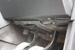
100 viewsRemoving dash undertray
|
|
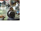
removing e-diff actuator904 views
|
|

Fluid, Filter/Pan Combo removal and install5949 viewsThese are the LR instructions re removal and install of the plastic pan/filter combo for the ZF 6HP26X transmission on the 4.4L petrol V8 LR3.
The instructions tend to ignore the reason you have to lift the right hand side of the engine about 40 mm. This is because of a frame cross member that interferes with dropping down of the plastic pan. The real problem is a vertical "oil filter spout" that rises out of the filter/pan combo up into the transmission. The spout is the suction pipe for filtered transmission oil back up into the tranny.
On the metal pan versions, the filter is separate from the pan, hence the filter remains with the tranny when the metal pan is dropped. The filter is then removed or installed independent of the metal pan, hence with the metal pan, there is no need to lift the engine.
If one is removing the plastic pan so as to install the metal pan, then some do not lift the engine but just drop the plastic pan enough to gain access to saw off the vertical plastic spout - it is a one time procedure.
Be aware however that the metal pan uses a flat gasket and the plastic pan uses a O ring like perimeter gasket that sits in a half round groove in the tranny casing. Also the metal pan uses 21 shorter torx M6x22.5 metric cap screws for the perimeter bolts. The plastic pan uses longer M6x28.5 torx metric cap screws.
|
|

Official instructions on how to remove the bumper906 viewsWhen removing the front bumper - you start with the front grill, then the headlamps, then the wheelarch trims, then the bumper...
|
|

disco3.co.uk instructions for removing wheelarches (with photos)641 viewsCourtesy of a senior member of the site - detailed instructs for removing the wheelarch trims and front bumper - use in conjunction with the other 2 documents
|
|

Official instructions on how to remove the wheel arch trims620 viewsWhen removing the front bumper - you start with the front grill, then the headlamps, then the wheelarch trims...
|
|

60 viewsFinal setup, everything in place after about one full day of work, which included removing quite some bits I had installed before.
|
|
Oops16 viewsThat's why it stopped moving forwards and started moving down!
|
|
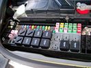
Picture of the engine compartment fuse panel5752 viewsEngine compartment fuse panel located near the battery. This is where F3E, (5 amp), F26E, (20 amp), Fuseable link 10E, (60 amp) and Relay 7E, the now upgraded 70 amp air compressor motor relay, part number YWB500220, (E is for Engine compartment fuse box), are all located. Fuse F35P, (5 amp), is inside the Passenger compartment behind the lower glove box door.
To keep the suspension from going down to the stops when driving, (or parked), it appears that it is only really necessary to remove F26E to depower the exhaust valve and generally keep all the valve block solenoid valves in a closed position trapping whatever air is within the air springs. F3E gets its power thru F26E, so when F26E is removed, the F3E circuit is automatically de-powered. F35P is more interesting in that battery power goes thru the ignition switch and F35P and then into the air suspension control unit. Apparently however, if F26E is removed, removing the F35P is not needed even when the engine is running.
With all fuses still in, if you have a problem, in practice, ideally, the compressor still works and will raise the 3 to an appropriate height. If so, one can then shut the engine off and allow the computers to go to sleep and then you remove the fuse(s). In actual practice, it seems that one need only pull the F26E fuse and can do so with the engine running. All the same, one might consider that the 3 is first a mobile computer, and secondly a 4x4. Computers prefer to go to sleep before the plug is pulled on them, however given that F26E circuit is always alive, then the computer never sleeps. With the fuse(s) pulled, and if you are still up, you can now be a 4x4 instead of a low rider. The whole purpose of the fuse pulling exercise is to depower the one and only system exhaust valve that is physically located within the compressor unit, (to keep it from opening), and secondarily to keep closed the four air spring solenoids within the block valves. This also shuts the air compressor down and stops the air compressor from making air even if the compressor is still good. That is why you initially need the fuse(s) in to allow the compressor to make air if it can.
|
|

Congestion on the M25 - Slow moving Dinosaurs....6 views
|
|

Handy for removing trees!!9 views
|
|
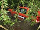
LRE Eastnor G4 D3579 viewsCALENDAR ENTRY
Photo taken during the LRW Show at Eastnor Castle, 6th June 2009.
The LR Experience G4 D3 was moving in to position to help out a stricken RR Sport that had gone off track and ended with its\' nose in the trees. A very impressive front (another LRE D3) and rear winching method to extract the RR Sport sideways followed.
|
|
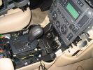
Removing the center console in preparation of installing the Drive+Play components.442 views
|
|
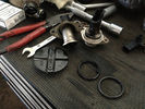
Butterfly valve and varous leftovers from the EGR valve blanking and pipe removing17 views
|
|

Thread upload11 viewsImage uploaded in thread 120780
|
|
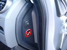
Air Suspension ECU Fuse 35P cut off switch.3802 viewsThis shows the SPST rocker switch mounted in the blank plate installed in lieu of a manual passenger side air bag shut down switch - now automatic via passenger seat pressure switch. Fuse 35P (5 amps) is located in the interior fuse box behind the lower glove box and protects the ignition power supply to the Air Suspension ECU. When the SPST switch is moved to the OFF position, the RAISE /LOWER switch on the centre console is not powered, and hence does not function. As such, some signals from the wheel height sensors and CPU are ignored. By itself however, removing F35P will probably not stop the 3 from self dropping, particularly after the engine is turned off.
Fuse F3E, (5 amps), located in the engine bay fuse box by the starting battery protects the circuit that provides feedback to the Air System ECU indicating that the Compressor Relay has successfully operated and that the Air Compressor is or should be operational, can also be removed, (but is probably not totally necessary), as it gets its power thru F26E. Hence Fuse F26E, (20 amp), also located in the engine compartment fuse box is the fuse that must be removed. This fuse protects the circuit that provides full time battery power to the Air System ECU. When in place, current thru the fuse powers the periodic re-levelling action, (usually lowering a bit with that brief air release noise), that often occurs when the vehicle is parked and the engine is off.
Removing F26E fuse will stop the auto levelling action and also inhibit any other down to the stops signals, (engine running or not). When F26E is removed, no power can flow thru to F3E, hence removing F3E is more for insurance than an absolute requirement. The same with F35P, removing F26E removes primary full time power from the Air Suspension ECU, and hence removing the F35P fuse should not really be required either as long as F26E has been removed.
|
|

Carpet Panel Removed showing Bass Speaker and Dust Shield 1722 viewsSomething is wrong with the orientation, however this shows what you see when the carpet is removed.
The dust shield, (under which the actuator is located), in the picture is as yet uncut. The white bit is the underside of the plastic lower lift gate carpeted cover panel.
The round thing is the woofer speaker for the Harmon Kardon radio. When the radio is working, one can see the speaker moving, but not much bass sound actually seems to emanate from the speaker.
|
|

Underhood Fuse and Relay Box drawing 3041 viewsShows the various fuse and relay locations. Fuse 3E, (5 amp), and Fuse 26E, (20 amp), as well as upgraded 70 amp Relay 7, part number YWB500220, locations are displayed. Relay 7 sends battery power to the compressor from the 60 amp fusible link called up as 10E. Fuse 26E is what provides full time always on battery power to the air suspension ECU and hence powers the auto level wakeup when the vehicle is shut down and say parked for the night. Removing F26E is the primary method to disable the air suspension system; Removing F35P is more if you want to experiment with it from inside.
I found it useful when I had a suspension problem, (actually a wheel alignment problem picked up by the steering wheel angle sensor), that only showed itself on the highway but allowed for no trouble light driving in the city. This was because in the city, the steering wheel was always in motion and rarely was the vehicle driven in a near straight line for very much distance.
|
|
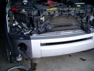
Wiring, (tubing), loom exiting temporarily from the front right fog light.566 viewsThe front axle air valve block is located just behind and below the fog light. Access to the valve block is by removing the right front fender liner, (or the bumper). The FASKIT lines are attached to the left and right front air spring lines at this location; also compressor air is taken from this location as well. Cutting the lines at as few different locations makes it easier to find leaks at a later date. As above, five 6mm air lines run from the FASKIT panel to the front axle air valve assembly and run within the loom. Two pair of the lines are for control of the air springs, and the fifth line taps the air supply at the valve block assembly off the compressor. This will be the air source line rather than tapping in directly to the high pressure air tank.
|
|

Land Rover Brake Light switch XKB5001102675 viewsThis is what the switch looks like when removed from the parts box. Note that the plunger is recessed back into the body and when installing, the process of rotating the switch body 1/4 turn anticlockwise releases the plunger so it pops longer and engages the brake pedal. If you look down on the plunger you can see curved slots where the rotation takes place.
Do not try to rotate the new one - play with the one you remove. Also do not press on the brake pedal when removing or installing as you will damage the plunger - this is one of the reasons the plunger is retracted into the body for installation. It is also for this reason that if you try to confirm the operation of the switch contacts with an ohm meter by pressing the plunger, the switch will appear not to function as one might anticipate. Have faith, the switch will however, once installed and the plunger is in full motion.
|
|
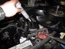
removing ps fluid from reservoir59 views
|
|
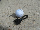
MOST fiber optic loop tool466 viewsThe looping tool in the jpg uses the Land Rover type plastic fiber optic cable with both ends feeding back into a female fiber optic connector that mates with the male fiber optic connectors on the Land Rover system.
The purpose of the loop is to allow one to disconnect MOST connected items such the BlueTooth module or the HK amplifier but allow the MOST system to still transmit signal from the head unit as the circuit would remain closed and hence complete. Of course with the Bluetooth module disconnected, there would be no Bluetooth available, however the radio and NAV would still function.
The looping tool allows one to troubleshoot the system by removing one component at at time from the MOST loop. In other words, what might appear to be a radio problem could be a Bluetooth problem - that sort of thing.
|
|
Thread upload0 viewsImage uploaded in thread 203150
|
|
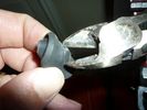
firewall plug run705 viewsThe rubber grommet from firewall plug, removed, with a hole cut in the middle. Instructions say to cut it to the center, but you can cut a hole out by bending it, and using a pair of diagonal pliers, removing excess material so you can fit the plug back in.
|
|
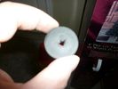
firewall plug run649 viewsThe rubber grommet from firewall plug, removed, with a hole cut in the middle. Instructions say to cut it to the center, but you can cut a hole out by bending it, and using a pair of diagonal pliers, removing excess material so you can fit the plug back in.
|
|
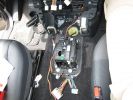
286 viewsPicture of the floor console removed. The wiring moving along from the bottom of the picture forward is power from the rear power socket, and audio from the aux port.
|
|

32 views
|
|

Removing rear panel87 views
|
|
477 views
|
|

73 views
|
|

430 views
|
|
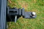
Shortened 298 viewsAfter removing 35mm from the tongue plug
|
|
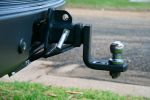
Shortened 98 viewsAfter removing 35mm from the tongue mount
|
|
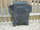
Lower engine bay tray313 viewsLower engine bay tray, 2006 Disco3 TDV6. Needs removing to gain access to sump drain plug.
|
|
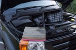
Removing air box is very easy, some screws and just loosen the jubilee clip around the air pipe147 views
|
|
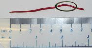
EPB Wire154 viewsThis wire came from somewhere in the EPB circuit and was the cause of my EPB not working. Circled in the picture is the broken part of the wire and just to the right of the break (also within the circle) you can just see a slightly thinner part where the wire has chaffed, removing the insulation.
|
|
|
|
|
|
|