| Search results - "sensor" |
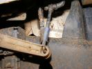
718 viewsFront height sensor - original is behind sensor arm, the new one is in the foreground.
|
|

Mucky Sensor101 views
|
|
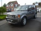
Disco 3 TDV6 GSLE75 viewsLimited Edition. Parking sensors front & rear, Full body skirts with chrome trim fog lights, Twin chrome tail pipes,
|
|

Thread upload43 viewsImage uploaded in thread 119357
|
|
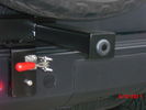
Sensor bar33 viewsSensor has been moved out to tire carrier where it should be. It does not pick up the tire anymore. "no faults".
|
|
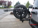
highlift and new sensor wire loom30 viewsNew wire loom added to protect sensor wires and keep things sanitary looking
. Highlift jack mount arms added and gas strut
|
|
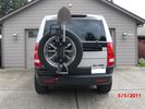
New mods for carrier. Backup sensor moved to the tire carrier. Toy rack and highlift mounts.38 viewsSon wanted all the toys on the carrier. I just wanted easy removal for a good clean look.
|
|
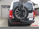
This is how to make it all work. Backup sensor on carrier43 viewsHighlift, ax and shovel. Yes they are matching colors. What else?
|
|

Receiver for toy rack38 viewsSensor bar was made of same heavy tube that the carrier was made from allowing a small 1 1/4" receiver to be placed on it for a multitude of toy racks of my choice. Rack adjust in and out of receiver.
|
|
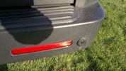
52 viewsSlight dink in parking sensor, caused by under sied trailor. Stops parking sensors from working and didnt see it. Bloody thing!! Parking snsor still working perfectly normal.
|
|
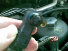
MAP sensor56 viewsMAP sensor gunky but hole clean. 108k miles non-blanked EGR.
|
|

Thread upload12 viewsImage uploaded in thread 159335
|
|
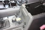
98 viewsAll 4 switches in place.
Driver's side switches are:
. Parking sensors master switch
. Reverse camera off/on/reverse-tiggered
Passenger side switches are:
. CarPC off/on/ignition-triggered
. 12V Regulator off/on/ignition-triggered
|
|
Dash Sensor22 views
|
|
map sensor15 views
|
|
humidity sensor 420 views
|
|
humidity sensor 321 views
|
|
humidity sensor 219 views
|
|
humidity sensor 120 views
|
|
humidity sensor 524 views
|
|
Windscreen sensor16 views
|
|

MAP Sensor before6 views
|
|

MAP sensor after5 views
|
|
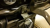
Position Sensor6 views
|
|

Thread upload9 viewsImage uploaded in thread 166901
|
|
Boost pressure sensor conn.2 views
|
|

Anti Lock and Traction Control description and operation.1968 viewsNote on page 6 of this 17 page pdf the significance of the Steering Angle sensor mounted on the steering wheel shaft. The paragraph regarding the plausibility check as related to the brake pedal being not depressed is why the clean operation of the second set of contacts on the brake switch matters so much.
|
|

Steering Column detailing Steering Angle Sensor1480 viewsItem 2 in the picture on page 1 of the 9 page pdf shows the location of the steering wheel sensor. Page 5 of the pdf has a paragraph describing the operation of the sensor. When the steering wheel does not point the same direction as the real wheels, then the computers can put the 3 into safe mode and down goes the suspension. See also the 17 page pdf on the Anti Lock and Traction Control pdf.
|
|
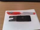
tool for changing height sensor rods114 viewsSimple, crude but it works
|
|
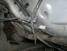
Left hand wheel sensors cable ends76 views
|
|
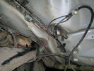
Front wheel sensor cables108 views
|
|

Thread upload0 viewsImage uploaded in thread 206795
|
|

Thread upload0 viewsImage uploaded in thread 206795
|
|
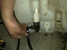
bottle with H/L washer pump and leveling sensor to the right - the space on the far right is for the w/screen pump83 views
|
|

Air Conditioning and Heater Control Components2376 viewsThis is a 21 page pdf that really explains how the air system is supposed to work. Discussed are the exterior ambient air sensor, where and how it operates; the interior temperature sensor as well as humidity sensor.
|
|

Wipers, Front and Rear, plus Washers description and operation.807 viewsThis 17 page pdf describes how the wipers, front and rear, plus the washers are intended to operate. Also described is how the rain sensor is designed to function along with a table of the wiper delay timing parameters.
|
|

Sensor-Height-Rear-LH65 viewsDescription: Sensor-Height-Rear-LH
Location: Below LH rear wheelarch
Part No.: YPC909530 Colour: BLACK Cavities: 3WY
Harness: CHASSIS HARNESS
|
|
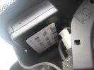
rain sensor behind mirror 1157 views
|
|

rain sensor behind mirror 142 views
|
|
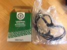
Thread upload20 viewsImage uploaded in new thread
|
|

Thread upload21 viewsImage uploaded in new thread
|
|
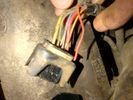
Broken wire Transfer box actuator motor harness 2 - temp sensor wire23 viewsBroken wire Transfer box actuator motor harness 2 - temp sensor wire
|
|
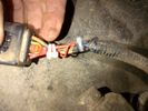
Repaired Transfer box actuator motor harness 2 - temp sensor wire22 viewsRepaired Transfer box actuator motor harness 2 - temp sensor wire
|
|
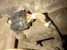
Repaired Transfer box actuator motor harness 3 - temp sensor wire23 viewsRepaired Transfer box actuator motor harness 3 - temp sensor wire
|
|
Thread upload15 viewsImage uploaded in new thread
|
|
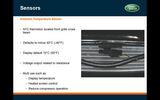
Ambient temp sensor136 views
|
|
back seat temp25 views
|
|

BMW Sensor Fit D3 fron24 views
|
|

Brakes Description and Operation2199 viewsThis is a 17 page pdf that describes the operation of the various braking systems: the ABS, CBC, DSC, EBD, ETC, EBA, EDC, and HDC. Also discussed is the yaw rate and lateral acceleration sensor as well as the steering angle sensor.
|
|
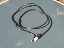
brake sensor cable5 views
|
|
Thread upload5 viewsImage uploaded in thread 132067
|
|
Thread upload7 viewsImage uploaded in thread 132108
|
|
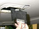
volumetric alarm sensor359 views
|
|
Thread upload10 viewsImage uploaded in thread 130551
|
|
CAM SENSOR7 views
|
|
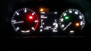
Car indicated temp30 views
|
|

Thread upload10 viewsImage uploaded in thread 166380
|
|

Thread upload7 viewsImage uploaded in thread 177857
|
|

Thread upload16 viewsImage uploaded in new thread
|
|
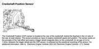
Thread upload9 viewsImage uploaded in thread 155238
|
|

MAP sensor29 views
|
|
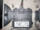
d3 alarm (inside sensors)168 views
|
|

Manifold absolute pressure sensor30 viewsCleaning the map sensor
|
|

32 views
|
|
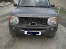
D3 with Radar sensor temporarily mounted57 views
|
|
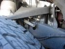
Picture of Height sensor borrowed from D3Matt238 views
|
|

D3_ECT_Sensor_Response16 views
|
|
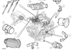
D3_Engine_Control_Sensors_Air_Charge_Temp_Sensor23 views
|
|
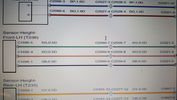
Thread upload15 viewsImage uploaded in thread 184914
|
|

D3_Oxygen_Sensor_Log12 views
|
|

Engine Coolant Sensor105 views
|
|
Thread upload29 viewsImage uploaded in new thread
|
|
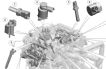
D4 Fuel Temp Sensor Location 315 views
|
|
Dash Sensor24 views
|
|
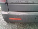
LHS sensor adhered to bumper195 views
|
|
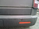
RHS sensor adhered to bumper194 views
|
|
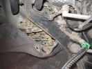
Brake sensor connector ( with 2 red wires connected)296 views
|
|

Thread upload13 viewsImage uploaded in thread 192177
|
|

Disco3 Suspension Height Sensor PDF90 views
|
|
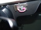
MY14 Humidity sensor windshield positioning18 views
|
|
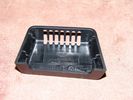
MY14 Humidity sensor cover11 views
|
|
MY14 Humidity sensor cabin side11 views
|
|
MY14 Humidity sensor windshield side11 views
|
|
67 viewsrainsensor as seen from outside. Note tinted film around sensor
|
|
Bonnet Sensor Paperclip26 views
|
|
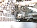
Water Temp sensor location928 views
|
|
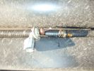
Defective sensor701 views
|
|
Fuel filter drain valve/water sensor33 views
|
|
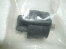
Fuel filter drain valve/water sensor30 views
|
|
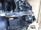
Front-right view (looking forward) of partially installed winch and mount122 viewsThe closest bracket, with three rubber grommets, is the air bag sensor. Before beginning any of this work, be sure to disconnect battery and discharge any remaining electrical power. I didn't want to accidently drop this assembly and cause the airbags to deploy.
|
|
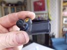
MAP sensor66 viewsgunky map sensor
|
|
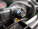
MAP Sensor43 views
|
|
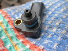
MAP Sensor38 views
|
|
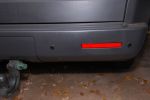
Through bumber reversing sensors333 views
|
|

Reversing sensor blackbox controller409 views
|
|
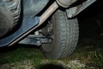
sensor27 views
|
|
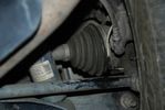
sensor 330 views
|
|
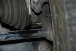
sensor 234 views
|
|
DVD Player63 viewsVeba DVD Player fitted into top glove box, AUX in for connection of Ipod, Games COnsoles etc. Remote control with sensor mounted by rear view mirror.
|
|
Thread upload3 viewsImage uploaded in thread 122907
|
|
Thread upload2 viewsImage uploaded in thread 982
|
|

Thread upload26 viewsImage uploaded in new thread
|
|
Footwell temp32 views
|
|

Front Inner Sensor Removal307 views
|
|

PDC - Front Inner Sensor Removal12 views
|
|

GOE Sensor Rod Installation12 views
|
|
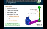
height sensors info121 views
|
|
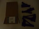
clearout height sensors0 views
|
|

Thread upload3 viewsImage uploaded in new thread
|
|
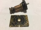
Thread upload1 viewsImage uploaded in new thread
|
|
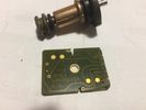
Thread upload1 viewsImage uploaded in new thread
|
|

Thread upload1 viewsImage uploaded in thread 197200
|
|
304 views
|
|

Thread upload2 viewsImage uploaded in thread 202238
|
|

Map sensor81 viewsBefore a good clean
|
|

Map sensor79 viewsBefore a good clean
|
|

Map sensor77 viewsAfter a good clean
|
|

Pad wear sensor removal77 views
|
|
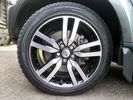
TPMS Sensor19 views
|
|

D4 Fuel Temp Sensor 114 views
|
|

D4 Fuel Temp Sensor 212 views
|
|

D4 ECT Sensor 214 views
|
|
MAP sensor116 views
|
|
Hole Drilled for Sensor109 views
|
|
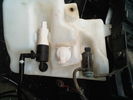
Sensor Fitted129 views
|
|
![Filename=IMG_0188[1].jpg
Filesize=118KB
Dimensions=1280x960
Date added=19.Jun 2010 IMG_0188[1].jpg](albums/userpics/15526/thumb_IMG_0188%5B1%5D.jpg)
Brake Sensor143 views
|
|

MAF sensor pre clean28 views
|
|

MAF sensor post clean29 views
|
|

Rovertym Height Sensor Rods109 views
|
|
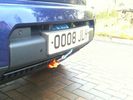
Redg plate mounting126 viewsThe original redg plate mounting was modified. An L-shaped piece of plastic now sticks out rearward from the top of the mounting and this hooks over the back of the top edge of the bumper cover. Then 2 spring clips hold the bottom edge of the mounting in place. Proximity sensor and surround camera seen unaffected.
|
|
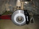
Brakes fitted122 viewsBrakes easy to fir - sensor replacement less so.
|
|
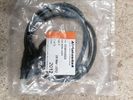
1 viewsFront Brake sensor
|
|

5 viewsd3 park sensors
|
|
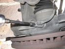
ABS position sensor65 views
|
|
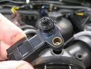
MAP Sensor38 views37,000 miles. EGRs replaced @ 22,000 & 29,000 miles.
|
|

Seat rail sensor on ex-driver seat to be transfered to new driver seat222 views
|
|
Seat occupation sensor from previouse passenger seat, now driver seat so took it out210 views
|
|
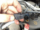
MAF sensor 8 views
|
|
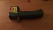
IR Thermometer15 views
|
|

LA100-003 - Technical Bulletin - Wheel Speed Sensor Concerns Diagnosis101 views
|
|

LA100-006 - Technical Bulletin - Sensor Cluster Fault Diagnosis75 views
|
|

LA204-003 - Technical Bulletin - Air Suspension Height Sensor Connector Overlay Harness120 views
|
|

Thermostat Housing LR005631527 viewsWhen the time comes to install a new thermostat, consider installing the whole housing instead.
Advantages are the thermostat is correctly installed, (not as simple as it should be); you get all new plastic and that is important, plus a new coolant temperature sensor and also a new heater coolant bypass valve, the secret part no one realizes is also within.
The cost of the whole assembly is not much more than the cost of a factory thermostat and the effort to replace all is not as difficult as it might seem.
|
|

LED trailer lights adapter for LR3831 viewsThis doc includes a partial list of materials and the instructions/links required to construct an adapter to prevent LED trailer lights from pulsing due to the 3's diagnostic circuits interrogating the signal light circuit.
Using the adapter also facilitates the green flashing of the dash located trailer indicator when the signal lights operate plus inhibits operation of various systems such as the backup sensors, etc.
|
|
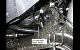
left hand rear height sensor108 views
|
|
Thread upload21 viewsImage uploaded in thread 74474
|
|

Bonnet Alarm Sensor13 views
|
|
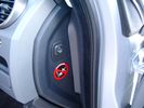
Air Suspension ECU Fuse 35P cut off switch.3802 viewsThis shows the SPST rocker switch mounted in the blank plate installed in lieu of a manual passenger side air bag shut down switch - now automatic via passenger seat pressure switch. Fuse 35P (5 amps) is located in the interior fuse box behind the lower glove box and protects the ignition power supply to the Air Suspension ECU. When the SPST switch is moved to the OFF position, the RAISE /LOWER switch on the centre console is not powered, and hence does not function. As such, some signals from the wheel height sensors and CPU are ignored. By itself however, removing F35P will probably not stop the 3 from self dropping, particularly after the engine is turned off.
Fuse F3E, (5 amps), located in the engine bay fuse box by the starting battery protects the circuit that provides feedback to the Air System ECU indicating that the Compressor Relay has successfully operated and that the Air Compressor is or should be operational, can also be removed, (but is probably not totally necessary), as it gets its power thru F26E. Hence Fuse F26E, (20 amp), also located in the engine compartment fuse box is the fuse that must be removed. This fuse protects the circuit that provides full time battery power to the Air System ECU. When in place, current thru the fuse powers the periodic re-levelling action, (usually lowering a bit with that brief air release noise), that often occurs when the vehicle is parked and the engine is off.
Removing F26E fuse will stop the auto levelling action and also inhibit any other down to the stops signals, (engine running or not). When F26E is removed, no power can flow thru to F3E, hence removing F3E is more for insurance than an absolute requirement. The same with F35P, removing F26E removes primary full time power from the Air Suspension ECU, and hence removing the F35P fuse should not really be required either as long as F26E has been removed.
|
|
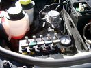
View of mounted panel from front left side872 viewsNote that all valve handles are shown in the OFF position, (the trouble position). In this case, the air that is in the air springs, (if any), is trapped in there - that is the valve blocks cannot vent whatever air is already in the air springs as the air lines between the springs and respective valve blocks are closed off by the FASKIT valves. In operation, there may be only trouble with one air spring, (perhaps a wheel height sensor), and as such, only one valve would need to be closed. If there was complete air compressor failure, then all valves would be closed and then as required, each spring could be manually filled from an outside clean dry oil free air source.
|
|

NAS 7 Pin Round Socket + 4 Pin Flat Socket oriented as installed.742 viewsThis is the layout you see when you look into the NAS Land Rover sockets as installed at the rear of the LR3/4. The flat 4 pin socket is located under the round socket.
Wiring order is relative to the slot on the round socket, and hence the same as the other jpg where the slot is shown at the top.
The CJB monitors the front and rear turn signal lamps and can detect if more than four lamps are fitted, (the side turn signal lamps are not monitored). This is another reason for using genuine LR bulbs as off shore bulbs can have varied and out of spec resistance values.
When a trailer is detected, the trailer warning indicator in the instrument cluster is supposed to flash green in synchronization with the turn signal indicators.
If one or more of the turn signal lamps on the vehicle or the trailer are defective, the trailer warning indicator will cease to flash any longer. This is to alert the driver to probably bulb failure.
If the trailer has LED lamps installed, and no LED adapter circuitry is used, most likely the trailer will not be sensed and systems such as the backup sensors will not be disabled.
|
|

Underhood Fuse and Relay Box drawing 3041 viewsShows the various fuse and relay locations. Fuse 3E, (5 amp), and Fuse 26E, (20 amp), as well as upgraded 70 amp Relay 7, part number YWB500220, locations are displayed. Relay 7 sends battery power to the compressor from the 60 amp fusible link called up as 10E. Fuse 26E is what provides full time always on battery power to the air suspension ECU and hence powers the auto level wakeup when the vehicle is shut down and say parked for the night. Removing F26E is the primary method to disable the air suspension system; Removing F35P is more if you want to experiment with it from inside.
I found it useful when I had a suspension problem, (actually a wheel alignment problem picked up by the steering wheel angle sensor), that only showed itself on the highway but allowed for no trouble light driving in the city. This was because in the city, the steering wheel was always in motion and rarely was the vehicle driven in a near straight line for very much distance.
|
|

Air Suspension Wiring Sheets3025 viewsThese two sheets show the wiring and fuses related to the operation of the air suspension system. Fuses F3E, F26E, and F35P are shown as well as the interior up down switch and the wheel height sensors.
As with all pdf's, you can rotate them to view plus download and or print out as you wish.
|
|

LR3 Brake Wear Sensor Wiring1488 viewsThis 1 page wiring diagram pdf shows that both the front and rear brake pad wear sensors are part of a closed series circuit to ground.
In operation, when all is good, the series circuit is grounded and the amber brake wear warning indicator on the instrument panel is not illuminated.
When the pads on one wheel, either the left front, or right rear, become too worn, the respective sensor is "cut" which results in an open circuit condition. This causes the dash brake wear indicator to illuminate.
The circuit is like the old style Christmas light strings where one burned out bulb caused the whole string to go out.
A quick field fix to get the dash light to extinguish in lieu of replacing the sensor and pads etc is to disconnect the brake pad wear sensor and short across the two open conductors of the vehicle side connector plug. This of course means you now have a normal vehicle, one of the thousands that do not feature brake pad wear information systems.
|
|

LTB00310 - Technical Bulletin - Air Suspension System - New Height Sensor Availability143 views
|
|

Thread upload14 viewsImage uploaded in new thread
|
|
17 views
|
|

9 views
|
|
Thread upload0 viewsImage uploaded in thread 202602
|
|
Thread upload13 viewsImage uploaded in thread 74474
|
|
Thread upload18 viewsImage uploaded in new thread
|
|
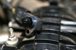
Map sensor @ 12 April 20137 viewsMap Sensor before cleaning
|
|

6 viewsMap Sensor @ 12 April 2013
|
|
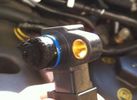
MAP sensor side41 views
|
|
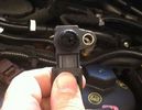
MAP sensor top39 views
|
|
Thread upload6 viewsImage uploaded in thread 64159
|
|
50 views
|
|
Thread upload8 viewsImage uploaded in thread 64159
|
|
46 views
|
|
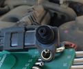
clean map sensor (erg blanked )12 views
|
|

Thread upload1 viewsImage uploaded in thread 64159
|
|
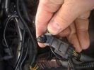
Map sensor115 views
|
|
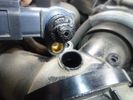
MAP Sensor67 views
|
|

25 views
|
|
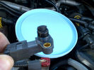
Dirty MAP Sensor13 views
|
|

Thread upload0 viewsImage uploaded in thread 192493
|
|

Thread upload8 viewsImage uploaded in new thread
|
|
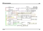
Thread upload15 viewsImage uploaded in new thread
|
|

10 views
|
|
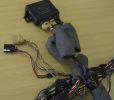
Missing PDC connector113 viewsThe front PDC sensor connector and wiring to the front had been removed.
|
|
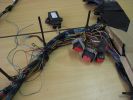
Yaw Rate Sensor98 viewsThe connector for the Yaw Rate sensor was missing and some rogue wires near the Airbag connectors.
|
|

Thread upload5 viewsImage uploaded in thread 189484
|
|

Oil Temp Sensor66 views
|
|

13 views
|
|
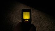
Outside ground temp14 views
|
|
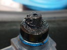
MAP sensor31 viewsmy sensor 115K
|
|
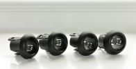
Parking Sensor Holders120 views
|
|
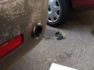
19 views
|
|

19 views
|
|
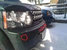
D486 views
|
|

Parking Sensors145 views
|
|

Thread upload76 viewsImage uploaded in thread 103415
|
|
Sensor Fault40 views
|
|
Sensor Fault36 views
|
|

MAP sensor 44k miles, EGR valves not blanked160 viewsUsed Miller's Sport 4 then whatever it has become, for last 22k
|
|
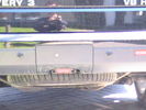
camera all installed - same size as a sensor381 viewscant go in centre of panel due to towing hoop
|
|
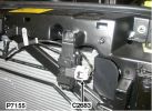
Pollution sensor379 views
|
|

161 views
|
|
Thread upload2 viewsImage uploaded in thread 199252
|
|

Service manual pdf32 views
|
|

PDC - Rear Inner Sensor Removal9 views
|
|

430 views
|
|
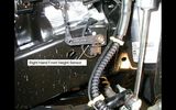
Right hand front height sensor93 views
|
|
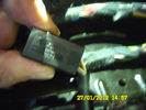
Heat connector76 viewsThis I found under the Dreaver seat. The connector says Ford Tyco This is for the heat element and the sensor I do beleave
|
|
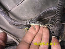
Extra wiring for height sensor52 views
|
|
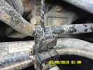
Height sensor not looking good62 views
|
|

h2o sensor 280 views
|
|

h2o sensor 168 views
|
|
Sensor mod114 views
|
|
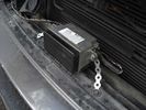
51 views
|
|
126 views
|
|

sensor11 views
|
|

Sensor19 views
|
|
Thread upload0 viewsImage uploaded in thread 122907
|
|

Thread upload9 viewsImage uploaded in thread 159736
|
|

Thread upload13 viewsImage uploaded in thread 163294
|
|

Thread upload7 viewsImage uploaded in new thread
|
|

Thread upload30 viewsImage uploaded in thread 193275
|
|

Thread upload1 viewsImage uploaded in thread 199255
|
|
Thread upload8 viewsImage uploaded in thread 106364
|
|

Thread upload2 viewsImage uploaded in thread 187842
|
|

Thread upload7 viewsImage uploaded in new thread
|
|
Thread upload6 viewsImage uploaded in thread 148831
|
|
5 views
|
|
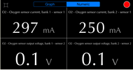
Thread upload4 viewsImage uploaded in thread 129776
|
|

Thread upload5 viewsImage uploaded in thread 163344
|
|

h2o sensor 64 views
|
|
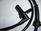
Thread upload1 viewsImage uploaded in thread 142777
|
|
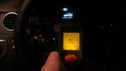
Steering wheel temp14 views
|
|

steering_angle_sensor_removal92 viewssteering_angle_sensor_removal
|
|
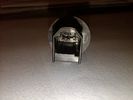
sunlight sensor92 viewssunlight sensor bottom sight showing three connection pins
|
|

81 viewsYep, the suspension failed! A sensor was to blame - dumped the air out ... nice! Easily fixed by the prompt arrival of LR Assist - thanks!
|
|
Thread upload1 viewsImage uploaded in thread 200279
|
|
Thread upload20 viewsImage uploaded in thread 114391
|
|

Tekonsha P3 Brake Controller 90195 to Ford 3035-P wiring adapter plug306 viewsThis two page pdf is the general instruction for hooking up the Tekonsha part number 3035-P adapter cable between a Tekonsha P3 controller and the existing Land Rover/Ford plug, (called C2590 in the Land Rover wiring diagrams), that is hidden above the brake pedal.
The "Ford" plug, (C2590), is grey and is stuffed up above the brake pedal arm.
Mount the P3 controller appropriately and then connect one end of the custom cable to the P3 and the other to the "hidden" plug.
You will now have power for your trailer electric brakes in the round socket at the rear of your LR3; also no computer update from the Land Rover T4 unit is required. For once, it is plug and play.
If however, your trailer has LED tail lights, you may have trouble with the flashing of the trailer signal lights or non recognition by the 3 that a trailer is connected. As such, the little green trailer signal will not illuminate when a trailer is connected and the signal lights are used. This can affect the shifting of the transmission and much to your annoyance, the backup sensors will still be functioning rather than being auto disabled.
|
|
644 views
|
|
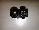
Temperature / humidity sensor91 viewsTemperature / humidity sensor fro the rear showing the two connecting pins
|
|

Thread upload19 viewsImage uploaded in thread 156161
|
|
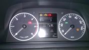
TPMS Errors12 viewsTPMS errors following hard reset by dealer in attempt to cure temperature sensor errors
|
|
Thread upload22 viewsImage uploaded in new thread
|
|

Very cold hands9 views
|
|
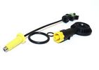
Water sensor19 views
|
|
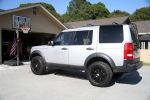
My LR3118 viewsafter new GY Duratrac's installed and modified rod sensors
|
|
Thread upload1 viewsImage uploaded in thread 982
|
|
Thread upload4 viewsImage uploaded in thread 199064
|
|
|
|