| Search results - "under" |
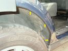
Arches rusting - now undersealed100 views
|
|

Arches rusting - now undersealed92 views
|
|
Thankfully it\'s nearly a week old. they wanted to dig underneath my drive to install gas. Nov 5th, Bang,78 viewsNo, and i was worried about the rangerover!
|
|
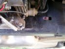
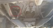
Repositioned compressor bracket735 viewsThe bracket was snapped in two, so I had it re-welded and slotted out the mounting holes so that it could be positioned 10mm higher (no longer protrudes under the chassis rail)
|
|
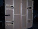
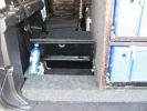
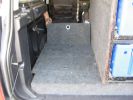
Sliding floor underneath29 views
|
|
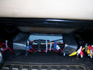
Units in place under pass seat117 views
|
|
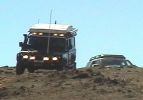
110 at Carinya Escapes ,Flinders ranges294 viewsDefender 110 Extreme,Long Range fuel tank,under floor water tanks, HF radio,GKN Overdrive,Swingaway Spare Carrier,70 litre Freezer,30 litre Fridge,Roof top Camper,Cruise Control,
|
|
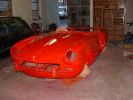
1970 Mk3 Triumph Spitfire (undergoing full restoration)671 views
|
|

Radio location537 viewsMy remote head UHF CB mounted on the front of the ashtray, ham HF/VHF/UHF remote head radio mounted on a block in the coin tray and my GPS on a turned wooden block in the cup holder. Both radios are under tha driver and passenger seat and the antenna for the GPS is suction mounted inside the windscreen.
|
|
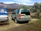
148 viewsUnderburg 2008
|
|

Virgin Snow127 viewsWent for a play in some new snow so I could practice and get my driving style right on close to zero friction surfces. Hard to tell from this photo, but car is parked on a 1:6 slope heading uphill, with hard packed ice under the fresh snow covering. I stopped here to practice my hill starts on ice...I was there for some time :)
|
|

160 viewsUnderburg 2008
|
|
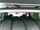
Thirteen Up84 views4 MTR\'s and 4 Sport 255/55 19\'s inside, One 18" Type 2 Mark 1 underneath and 4 18" Type 2 Mark 2\'s on the road
|
|
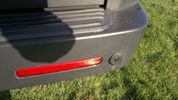
52 viewsSlight dink in parking sensor, caused by under sied trailor. Stops parking sensors from working and didnt see it. Bloody thing!! Parking snsor still working perfectly normal.
|
|
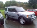
Pre-delivery ...... Plates still under the wiper blades152 views
|
|
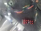
Under seat loom - manual118 views
|
|

Under seat connector - manual121 views
|
|
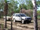
D3 in Kakadu National Park, on the track into the Alligator Billabong47 viewsThis whle area is down on the flood-plain, so in the Wet it is all under a few inches of water. In the dry it has a hard but brittle surface, which is then chewed up in many places by the feral animals with hard hoofs such as buffalo, pigs and horses. This then turns the track into a big dust bowl which is primarily bull-dust - a soft fine powder like talcum powder, which can be many feet deep, and gets into everything. The cover on the trailer is actually black.
|
|
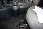
92 viewsStuffing cable under the floor console
|
|
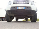
Under wiew67 views
|
|

KR switch cover drilled115 viewsNow I can see the LEDs underneath!
|
|
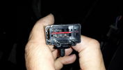
Connector on underseat harness for heated rear seats16 views
|
|
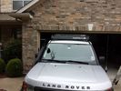
low profile solar panel203 viewsThe low profile solar panel, can be seen here, as the fine white line under the light bar. The way it's laid out, the panel should generate decent power between 10am and 4pm depending on the time of year, from the sides or front, with no shadows. Grape Solar 100W flex panel.
https://www.facebook.com/DifferentialPartsUS
|
|
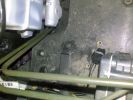
Area where Alarm Sounder was originally fixed94 views
|
|
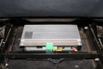
03284 viewsStock amp, underneath passenger front seat. In order to integrate the factory head unit with the V1000 we had to go through the stock amp. This is because of the MOST (fiber optic) connection between the two.
|
|

Running Cable Through Rear - under seats126 views
|
|
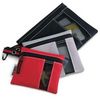
Husky Organizer Bags120 viewsUse these or something similar if you own a refrigerator cubby box and want to use it for storage and occasional fridge. They go for under $7.00 at Home Depot.
|
|
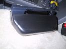
Ham Radio446 viewsThe remote head of an Icom IC706 was mounted on a piece of wood shaped to fit into the coin holder. This is quite a tight fit and does not shake loose. The radio is mounted under the driver seat.
|
|

Land Rover Aerial Fin images for both Glass and Metal Roof Disco3 / LR3850 viewsAs well as the two different fins, this pdf also shows the plastic blanking plate for glass roof vehicles where no fin is installed.
The glass roof fin is secured by two security screws from the top into a plastic frangible glue on gasket. The hope is that when struck, the fin will shear off and not crack the glass roof. Re the metal roof design, the fin is secured from underneath via two nuts.
The pdf also shows the various electrical bits related to the antennas. In the UK, the fin would house not only a cell phone antenna but the TV and satellite radio antenna electronics as well; in the States, the Sirius sat radio antenna and a G type cell phone antenna if the phone kit was installed would reside within the fin. The SAT NAV GPS antenna is located within the High Mount Brake Light plastic mounted to the upper rear hatch.
|
|
409 views
|
|
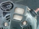
Alternator Plug and B+ terminal910 viewsPictured is the rear of the older Land Rover part # YLE500190 alternator showing the shiny cooling fin of the Regitar VRH2005-142 regulator under.
The first pin in the far left side of the connector is numbered #1 in the LR electrical wiring diagrams and is Battery Voltage Sensing (BVS); the middle pin, #2 receives a Pulse Width Modulated (PWM) signal from the Engine Control Module (ECM), and the right pin, #3 carries a PWM signal back to the ECM. Terminal Pin #2 on the LR wiring diagrams is called Alternator Control or ALT CON; Pin #3 per LR is called Alternator Monitoring or ALT MON.
Pin #1 is similar to what in older designs used to be called A or Batt, but is now called by Denso, S, AS, or Alternator Sensing for this design. Pin #1 also provides power to excite the alternator at startup until the PWM instructions over ride the battery voltage info. Land Rover calls the electronics under the pins a Smart Regulator, ironic, as it has to follow orders from the ECM rather than give the orders - new age thinking I guess. This is different from older design internal regulators that look at just the battery or the electrical buss voltage and then decides itself what to do.
It is almost like we are back to the external regulator designs of old, except that the ECM may decide that instead of telling the alternator to make more power, to load shed, and hence shut down the heated windscreen, seats, or whatever other electrical loads it decides are appropriate. My view is that the "smarts" are in the ECM and that the "regulator" should be regarded if not dumb, then as being a slave to the ECM.
|
|

Thread upload4 viewsImage uploaded in thread 183933
|
|
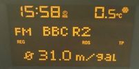
Astra 1.6 fuel consumption29 viewsFuel consumption of a 1.6 petrol Astra after a return trip from Aberdeen to Peterhead.
And yes I know i am sad listening to radio 2, but it was the only station I could understand up there.
|
|
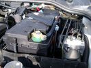
Aux Battery showing ground cable bolt "upside" down 1568 viewsIn order to obtain sufficient height clearance to get the plastic cover back on, I had to install the ground cable to the underside of the battery post connector.
Note the battery vent hose, (approx 5 ft required) is run down into where the windshield washer fluid container is located. There is not much electrical or metal in that area to be corroded by battery gas plus the open end of the vent hose tends to be protected from dirt and stays clean as well.
|
|
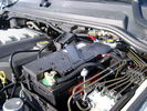
BCI Group 40R Deka 640RMF battery showing vent hose run forward to windshield washer reservoir area 1424 viewsRecessed post "Euro profile" battery to "match" OEM and stock Land Rover bracket; note that the Traxide SC80-LR module is mounted at an angle to allow for the main cable to sit under the cover so cover still closes.
The battery is a nominal 7", (180mm), high, but sits on a 1" battery spacer set under to raise the bottom front end of the battery such that the approx 11", (290 mm), length of the BCI 40R battery rises above the angled plastic nibs at the forward end bottom of the case front; hence sufficient space, (1/4", 5mm) remains at the brake reservoir end.
Also the 40R battery does not have hold down "flanges" on each end; on the sides yes, but not the ends so no additional length is required.
When I had to replace the 40R, this time I installed the shorter, (9.625"), taller, (7.5") Interstate BCI 47 / DIN H5 battery which eliminated the spacer on the bottom and better fit the stock LR tie down bolt lengths. Deka also has a BCI 47 / DIN H5 that would work fine as well.
|
|

Frame Jacking Points showing where holes are located.1078 viewsThe four points marked with the arrows show where the holes in the underside of the frame are located such than one could insert a trolley jack pin type lifting adapter, (or as designed), the official LR scissors jack.
|
|
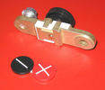
Battery Disconnect side post with + & - caps under view738 viewsThe upper and lower pieces of metal are clamped together but electrically seperate from each other. The connection between the two pieces is via the threaded part attached to the knob. When the knob is turned tight, current will flow between the two sections of metal.
|
|

Black Deposits to interior of Brake Light Switch2833 viewsThere are two contacts, one on each side of the vertical plunger under the copper metal. The set of normally open contacts on the left side that carries the power for the brake light filaments, (15 amp fuse F15P), is apparently not heavy enough as the contacts deteriorate and generate the black residue.
The set of normally closed contacts on the other side appear to be sized OK. There is not as much current, (5 amp fuse F66P), flowing thru the contacts to the ABS module, however the contacts are likely adversely affected by the black residue produced by the other deteriorating set of contacts.
One presumes/hopes that the newer replacement switch now has contacts heavy enough to carry the brake light power. It would be ideal if the ABS set of contacts were sealed from the brake light contacts to prevent contamination of the normally closed set of contacts.
|
|
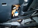
Smooth Talker Amplifier Box mounted below near steering column.179 viewsThe gold look box due to the lighting, (actually black), is the antenna amplifier located near the steering column. It can be put anyway but this seemed an OK location as I ran the antenna connector cable rearward from here to the back corner of the 3 and then up to the underside of the roof glass at the rear. The blue/white thing is the brake light switch that often must be replaced. See the Brake Light Switch file within this Gallery regarding the switch replacement.
|
|
LH cable tucked under ribbed bumper plate160 views
|
|
RH cable tucked under ribbed bumper plate163 views
|
|

Thread upload22 viewsImage uploaded in thread 92518
|
|

Thread upload26 viewsImage uploaded in thread 92518
|
|
![Filename=captain_underpants_2[6].jpg
Filesize=16KB
Dimensions=259x194
Date added=18.Nov 2014 captain_underpants_2[6].jpg](albums/userpics/10700/thumb_captain_underpants_2%5B6%5D.jpg)
Captain Underpants23 views
|
|
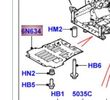
8 views
|
|
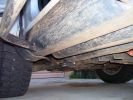
Sill protectors796 viewsThese replace the plastic sill protectors. 4mm mild steel plate, bolted through the existing holes in the side and underside.
|
|
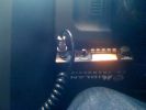
204 viewsCB location under steering wheel to left.
|
|

Brackets fitted to underside of A bar using mounting bracket holes.251 views
|
|
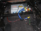
GVIf module under seat33 views
|
|

D3 and D4 Underbody Protection inc. bracketry 115 views
|
|
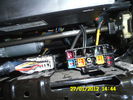
Connector under seat103 views
|
|
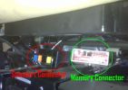
Under seat connectors80 views
|
|
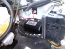
CounterAct Power Supply mounted 244 viewsPicture is blurred, however power supply is 3M two sided tape to the flat black plastic of the second battery compartment just under the antilock brake pipes to the fender side of the brake fluid reservoir. The white wire to the left rear coupler pad runs thru the firewall hole near the steering column. The blue wire to the right front coupler runs across and above the engine following the other wiring looms that cross the vehicle.
|
|
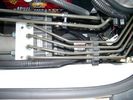
CounterAct Power supply mounted under brake lines.191 viewsThis top view shows where I located the power supply. It is attached with 3M sticky to the black plastic surface that is located under the brake lines.
When the system is operating properly, the red LED pulses about twice per second.
Some users claim they can hear a very slight hum or whine coming from the unit. My unit seems silent.
|
|

Thread upload2 viewsImage uploaded in new thread
|
|

25 viewsCERS Founder and China's 'greatest living explorer' Dr Wong How Man joined the Journey of Discovery in Dunhuang, China - a symbolic intersection of the Silk Road where the East meets West.
Interactive Land Rover MENA
|
|
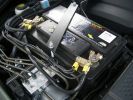
2nd battery in engine bay. Look under the rigid brake lines to see the solenoid434 views
|
|

30 views
|
|
312 views
|
|
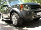
Underbody Protection Plate203 views
|
|
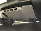
Underbody Protection Plate194 views
|
|
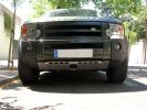
Underbody Protection Plate178 views
|
|

Chris 200100\'s Alarm instructiosn with pic from JKP & Simon493 views
|
|
Thread upload1 viewsImage uploaded in thread 164697
|
|
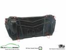
Thread upload5 viewsImage uploaded in thread 184516
|
|
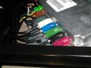
Under seat module148 views
|
|

Thread upload7 viewsImage uploaded in thread 152593
|
|
Thread upload3 viewsImage uploaded in thread 184516
|
|
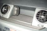
Mitac Mio Cradle445 viewsMitac Cradle adapted to fit to L shaped bracket (remainder sits under rubber mat) Allows PDA to be quickly removed when leaving the car unattended.
|
|
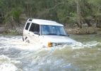
100 viewsIf you leave a D3 in the water for too long, all the panels disolve and you find one of these underneath!
|
|

Deka Battery Dimension Data613 viewsThe battery size that I installed for my auxiliary was a BCI 40R battery as it was for me the easiest to fit and was also a cranking battery. The case profile was such that no tie down fins were located on either bottom end, (sides yes), and length wise, it was only about 11" (290 mm) long. As such, I did not have to grind the nibs at the front bottom of the plastic surround.
I did however raise the bottom of the battery above the angled nibs as I set the battery on a 1" (25mm) high plastic spacer. The total height, (battery plus spacer), was about 8" (200mm) so the battery top still fit under the Land Rover factory cover.
For the Aux battery, when I replaced the 40R, I installed an Interstate BCI 47 which is similar in size to a DIN H5. I was therefore able to eliminate the vertical spacer as the Group 47/H5 is the same height as the DIN H7/H8 stock LR spec starting battery. As such, the standard battery tie down bolts can be used without modification. The Group 47 battery is 9 11/16" long x 6 7/8" wide x 7 1/2" (190mm) high.
|
|
385 views
|
|
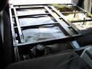
water tank276 viewsTank in position under subframe.
|
|
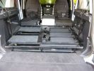
water tank353 viewsFlip up doors for extra storage under sub frame.
L.H.S covered with carpeting.
|
|
Rear lid320 viewsRear storage compartment, under sub frame.
|
|
Inner lid259 viewsStorage compartment, front, under subframe.
|
|
Thread upload6 viewsImage uploaded in new thread
|
|
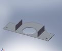
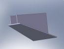
Discovery 3 rear underbody protection109 viewsDiscovery 3 rear underbody protection wich I designed and draw.
|
|
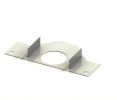
Discovery 3 Underbody protection122 viewsDiscovery 3 Underbody protection
|
|
Discovery 3 Underbody protection108 viewsDiscovery 3 rear underbody protection wich I designed and draw.
|
|

Thread upload7 viewsImage uploaded in thread 150930
|
|
Thread upload1 viewsImage uploaded in new thread
|
|
Thread upload1 viewsImage uploaded in new thread
|
|
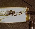
Actuator box underside 62 viewsUsed a clove hitch with plastic zip tie with 1/8" Kevlar rope
|
|
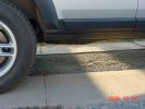
King Springs Lift216 viewsRear underbody Clearance
|
|
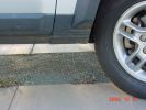
King Springs Lift203 viewsFront underbody clearance
|
|
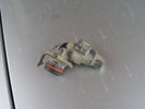
Object under skid plate 238 views
|
|
Object under skid plate39 views
|
|
Tools under tailgate200 views
|
|
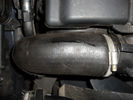
63 viewsPART NUMBER PNH/500024 D05WA >CR<
FAULT CODE UNDER TDV6 DISPLAYED IS P0299 DESCRIPTION DISPLAYED UKNOWN BUT IS I THINK (UNDER BOOST)
|
|
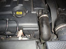
intercooler hose split49 viewsPART NUMBER PNH/500024 D05WA >CR<
FAULT CODE UNDER TDV6 DISPLAYED IS P0299 DESCRIPTION DISPLAYED UKNOWN BUT IS I THINK (UNDER BOOST)
|
|
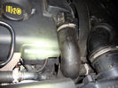
Split Intercooler Hose49 viewsPART NUMBER PNH/500024 D05WA >CR<
FAULT CODE UNDER TDV6 DISPLAYED IS P0299 DESCRIPTION DISPLAYED UKNOWN BUT IS I THINK (UNDER BOOST)
|
|
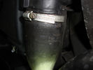
38 viewsPART NUMBER PNH/500024 D05WA >CR<
FAULT CODE UNDER TDV6 DISPLAYED IS P0299 DESCRIPTION DISPLAYED UKNOWN BUT IS I THINK (UNDER BOOST)
|
|
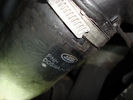
47 viewsPART NUMBER PNH/500024 D05WA >CR<
FAULT CODE UNDER TDV6 DISPLAYED IS P0299 DESCRIPTION DISPLAYED UKNOWN BUT IS I THINK (UNDER BOOST)
|
|
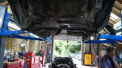
Body Underside17 views
|
|

After and off.267 viewsClean underpants were also required
|
|
Damaged area66 viewsPic shows plastic breather fitting with the corner ground away. When tank reached full fuel is pushed out under forecourt pump pressure. The second occurrence shows similar damage.
|
|
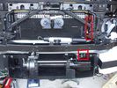
Installed winch with hydraulic hoses175 viewsThe hydraulic hoses are stiff, so I had to run them up the side of the radiator (can just see inside red boxes) to near the top of the radiator, then back down inside the engine compartment, then underneath the engine (behind the radiator) to the D4's power steering rack, where the hoses become metal. This hose routing may not be possible if the fuel-burning heater is in place (we don't have those in Aust and the space allowed room for my hands to bend and run the hoses without kinking).
|
|
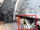
Further detail of attachment of the winch hoses to power steering system140 viewsThis is under the right (looking forward) lower plastic radiator cover.
|
|
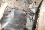
49 viewsLooking up under the wheel arch with the cover held back
|
|
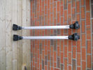
Underside of bars.20 views
|
|
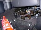
Mounting a non-LR fire extinguisher531 viewsShowing the plastic cover removed. I will make up a metal plate or bar so that the extinguisher frame can be mounted directly to this framework under the seat.
|
|
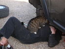
Under Supervision 132 viewsChanging front ARB bushes.
|
|
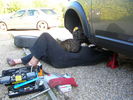
Under Supervision 229 viewsChanging front ARB bushes.
|
|

416 viewsCALENDAR ENTRY
Off-road obstacle maneuvering under misty hills
|
|
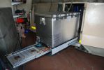
built fridge slider in front door (as opposed to rear) which makes fridge available at the kitchen. Also added drawer for gas stove - stows easily under the fridge when not in use. can be used independantly of fridge, ie. whether fridge is pulled in or ou113 views
|
|
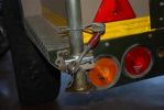
fitted stronger rear strut holders. not a great mod. the holes i drillled for the "R" clips are the best mod, as they stop the legs from sliding up under pressure. requires bracing inside to stop chassis bending100 views
|
|
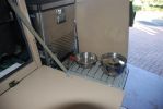
gas stove slides out under fridge107 viewsvery useful mod - youdon\'t have to unpack anythinig to be ready to cook. the stove gas is piped from the rear of the trailer, ie. the standard gas cylinder. pipe goes thru grommets along bodywork, and uder the fridge. works a treat. the door adds shielding in high winds if need be
|
|
Underside f roof mount antenna344 views
|
|
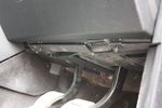
100 viewsRemoving dash undertray
|
|
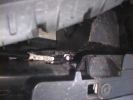
The swinging lump of iron that sit under the back,867 viewsLook how close it is to the wiring!
|
|
Thread upload6 viewsImage uploaded in thread 152593
|
|
Wires under the bonnet 142 viewsLooking inside the grille - centre. No socket here.
|
|
Wires under the bonnet 141 viewsLooking inside the grille - centre. No socket here.
|
|

CALENDAR 2008665 viewsDisco 3 under the rainbow. Near Bahia Blanca (Argentina)
|
|
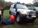
Slimer demonstrating his prowess with his airbag!264 viewsneo was inspecting the underside at the time - not sure why?
Allegedly a 4 ton airbag was needed since the boot was full (and I can confirm this) of crates of Desperado
|
|
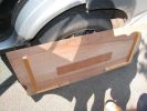
Underside showing various thickness of packing135 views
|
|

Wiring Diagram Fog Lamps76 viewsR130 is the (R5 relay under the hood) The wire is blue grey that is hot when the high beams are on and opens the relay contact that turns off power to the fog lamps. North America Only
|
|
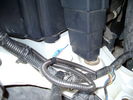
Front coupler pad to right front under air filter housing 158 viewsCoupler Pad is attached to the flat metal surface just behind the rectangular drain off of the air filter housing. The last 3 inches (75mm) of the 1/4" (5mm) black flex wiring loom was then threaded over the last bit of wiring. One of the other jpg's is less washed out and shows the coupler pad a bit better.
|
|
Front Coupler pad to right front under air filter housing 155 viewsThe brighter white "square" behind the black air cleaner drain is the Coupler Pad location I chose for the right front corner. The 1/4", (5mm), black wiring loom carries a single blue colour conductor between the power supply and pad.
A second coupler pad, (white conductor), is located near the left rear tail light. The mounting location is accessible from the rear compartment access "door" where the trailer hitch wiring attaches to the factory loom.
|
|
Blackthunder at her nest!1078 views
|
|

Series LR at Oil Sands Plant in Northern Canada circa 1968742 viewsThis is an end of shift picture taken about 1968 at the Great Canadian Oil Sands (GCOS) plant while under construction in the Ft McMurray area of Northern Canada.
I was surprised to see the yellow coloured Series single cab hardtop pickup parked in about the centre of the picture. I would say it is one of the few on site as most vehicles were Chevrolet's, (as are the other three trucks elsewhere in the view). The yellow painted vehicles including the Land Rover are most likely Bechtel owned - not leased - yes, that long ago now.
|
|

Thread upload11 viewsImage uploaded in new thread
|
|

Roy Keane leaving Sunderland103 views
|
|

Glovebox 1141 viewsLocated D&P box on underside of glovebox, same as LR iPod/MP3 box
|
|
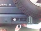
387 viewsconcept for Hayman Reese tow bar - bolts on inside bumper channel - need to remove bumper to fit - won\'t work with tyre underneath - concept only - but will be building prototype week of 9/7.
|
|

Drive & Play148 viewsFitted the screen using a piece of laminate flooring fibreboard underlay & cutting up a 3.99 leatherette cushion, looks like it was fitted from new
|
|

Earth or -Ve connection required under Driver Seat. Cut the green and black and splice into the blac.130 views
|
|
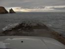
Couldn't resist a Thunderbird 4 moment !162 views
|
|

Couldn't resist a Thunderbird 4 moment !175 views
|
|
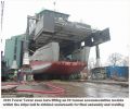
Messing with boats112 viewsShows our 300t capacity Lift System holding up an 80 tonnes module as the hull is winched underneath for final lowering and welding together.
|
|

Side Protection Bars - underneath36 views
|
|

Underside of the ciruit board127 viewsThis looks more of a mess than needed to be. The Maplins guy tried to be helpful when I bought the relays, he wrote down the switching COM/NO/NC, it was actually NC/COM/NO. Some scratching of head when it didn't work then worked out what happened when I looked on the manufacturers website at the data sheet...lesson of the day check the data sheet!
|
|
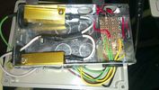
Underside137 viewsThe underside of the inside box. Resistors are 6 ohms with a power rating of 50w, don't be tempted to get the lower power rating.
|
|

Underside104 viewsStrapping threaded and rubber feet added, to the alloy frame made for it to sit in
|
|
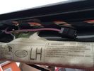
Under A pillar13 views
|
|
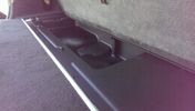
Under floor storage18 views
|
|
Under A Pillar 13 views
|
|
Dent on bottom of side bars - you can see powdercoat and steel underneath140 views
|
|
Underside View of Jet/Retainer Clip121 views
|
|

Switch is blue colour thing thru the rectangular opening.3149 viewsThe blue coloured plastic bit thru the rectangular opening is the brake light switch. The fist time, I found it easier remove the switch by dropping the horizontal plastic panel, (two screws), and then slipping my hand in and rotating the switch clockwise 1/4 turn. The second time, I was able to remove the switch thru the rectangular opening and did not need to remove the horizontal lower panel. Obviously, I had to remove the sloping knee pad panel, (note sort of hinged at the bottom so pull back from the top.)
Regardless, do not touch the brake pedal - just let it sit where it wants to. One has to first remove the angled knee pad panel that sits under the steering wheel. It can be pulled from the top corner at the door side. Pulling releases a pair of those U shaped metal clips that LR loves so dearly. You have to pull quite hard. The bottom is held by a couple of plastic fingers in a couple of slots so you pull at the top till the two clips release and then rotate the panel and pull upwards a bit.
To remove the switch, you rotate it clockwise and pull outwards. Rotating the switch clockwise automatically retracts the plunger back into the switch body away from the brake pedal arm.
Similarly when you install the new switch, the required 1/4 turn anti clockwise rotation action releases the plunger so it lays up against the brake pedal arm and at the same time, secures the switch in place.
To remove the electrical wires, the switch will drop below the horizontal pad and hang from the wires so unclipping the electrical connector plug is fairly easy to do.
|
|
Underneath platform - bolts to seat mounts. T-nuts to through bolt fittings174 views
|
|
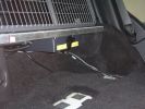
HF radio under rear floor (5 seater)166 views
|
|
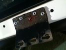
A pillar mount pop-rivetted in place and form-a-gasket used to seal underneath161 views
|
|

underbody guards54 views
|
|

Christmas Presents under the tree..... Don't worry we're guarding - who's on watch, Teagan or Lola?15 views
|
|
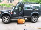
Bushranger test @ home179 viewsThe third trial proved succesful, but I still should have placed it a bit more underneath the car itself
|
|

My underside384 viewsCheck out the full skid plate! It sacrificed itself for the LR. This event would have been dangerous without it...
|
|
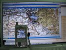
TTQV and PathAway on a Mac...384 viewsThat picture was taken as I was using TTQV from Touratech on a Mac running Windows XP SP2 under Parallels Software beta... The mobile is a Palm Treo 650 running PathAway...
|
|

Hidden Parking in France44 viewsThe Ultimate Undercover Disco
|
|
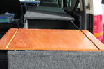
50 viewsUnderside of table top. Grooves created by a router to stop every thing sliding off. Marine Ply. My birthday present!
|
|
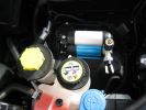
ARB under bonnet air compressor285 views
|
|

My D3 undergoing Tilt Training135 views
|
|

Under-vehicle wiring574 viewsUnder-vehicle wiring on Discovery 3
|
|
Under body wiring631 viewsUnder body wiring on Discovery
|
|

Under Drivers Seat - Connector box (being opened)44 views
|
|

Under Drivers Seat - Connector box38 views
|
|

Under Drivers Seat - Element connector31 views
|
|
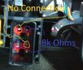
Under Drivers Seat - Element connector - Annotated43 views
|
|

New Exide AGM battery - Varta silver/calcium battery was replaced under warranty at 79680km.30 views
|
|

Frontrunner Sump Guard Fitted9 viewsSGLD009
https://www.frontrunneroutfitters.com/en/be/protection-equipment/under-vehicle-protection/land-rover-discovery-2014-present-sump-guard-4-5mm-3cr12-stainless-steel-front-runner.html
|
|
under12 views
|
|
under10 views
|
|

underside of canvas10 views
|
|
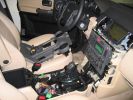
This is what it looks like under the center console at the beginning of my project.465 views
|
|

UHF Antenna Mount384 viewsView from underside of bonnet. The lower half of the mount is folded from stainless steel and bolted through an exisitng oval shaped hole in the bonnet. This hole is throught the heavy steel plate that the bonnet hinges bolt to - not just the aluminium panel. A specially machined rectangular nut was made to pass through the oval hole, rotate 90 degrees and then stopped from turning by a slight shoulder on the nut.
|
|

folding back the Caranex under a HEAVY rain, funny indeed459 views
|
|

EGR replacement17 viewsCarbon build up under the flange in the sliding shaft
|
|
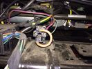
Under Seat15 views
|
|
Harmon Kardon Audio Amplifier10 viewsLocated underneath right hand front seat. Connected to MOST system
|
|
AT2 Grabber in Dunes266 viewsin extended mode, at rest, with AT2 tyres. Tested at Atlantis Dunes with flying colors.
Mantec non-winch plate visible.
|
|
undervody with old intercooler hose9 views6 years and 92,000 kms later, my intercooler hose was about to be replaced
|
|
this is how the underbody looks like with my old intercooler hose10 views
|
|
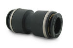
John Guest DOT all plastic fitting714 viewsThis is a picture of the John Guest DOT all plastic union. If you look closely, you can see the DOT imprinted in raised letters on the end of the fitting. This is of a 1/4" connector rather than the 6mm that the 3 requires.
The picture is similar to the air suspension pneumatic fitting union that Land Rover sells as replacement part # STC8580. This is for 6mm OD tubing size. The STC8580 comes with what are called "Collets" at each end that cover up the press to release feature underneath. See the John Guest web site www.johnguest.com under the Pneumatics section and also in Downloads for their catalog for install and remove instructions.
The actual "air brake spec" fitting that Land Rover provides has an interior 4mm OD ferrule that slips inside the 4mm ID of the nominal 6mm tubing. I have not yet been able to obtain the John Guest part number for the LR fitting, only the LR part number. This part number was generated for the RR Classic air systems.
|
|

John Guest (LR part # STC8580) push in straight 6mm tubing to tubing connector727 viewsThis picture is similar to the air suspension pneumatic fitting union that Land Rover sells as replacement part # STC8580. This is a 6mm OD tubing size push in to install straight tubing to tubing fitting. The STC8580 comes with what are called "Collets" at each end that cover up the press to release feature underneath. See the John Guest web site www.johnguest.com under the Pneumatics section and also in Downloads for their catalog for install and remove instructions.
The actual fitting that Land Rover provides has an interior 4mm OD ferrule that slips inside the 4mm ID of the nominal 6mm tubing. Hence the fitting depicted and part number are not actually correct. I have not yet been able to obtain the John Guest part number for the LR fitting.
The fittings that show in this doc are what I call food service fittings rather than transportation or Air Brake fittings. The part LR sells, (STC8580), is the Air Brake type for transportation.
|
|
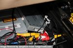
GVIF Box Under seat64 viewsIt had been covered by a plastic cover removed for the photo
|
|

On the Birdsville Track135 viewsStoped for a dingoes breakfast, a quick pee and a look around,also just checking whats under the bonnit of the D3,dont know so just shut it.
|
|
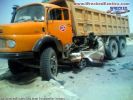
thats a landcruiser under there!!!277 views
|
|

Thread upload7 viewsImage uploaded in thread 150930
|
|
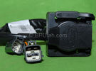
Harness section that runs behind the rear bumper.405 viewsThis is the harness section that clips up inside the rear bumper and includes the circular 7 pin, (6 flat +1 round), NAS socket, and also the 4 pin NAS flat connector.
The two small plug ends connect under the rear left tail light to the harness section that exits from the interior.
The Land Rover part number for the NAS trailer tow kit, (both cables), is YWJ500220.
|
|

2011 Lincoln MKX - Ford Edge underneath24 views
|
|

LR3 Air Conditioner Drain Tubes behind centre console2092 viewsThis shows the two air conditioner drain tubes located left and right under the radio stack.
The tube on the left side, (steering wheel side, LHD), disattached itself and the carpet on the floor under the gas pedal etc became soaked. I think rain water from outside that comes in the outside cowl vents also exits via the tubes as I first noticed the carpet was wet after parking outside during a big rain storm.
It was relatively easy to slide up and reattach the rubber hose that runs from the rectangular shaped plastic discharge hole(s) of the heater "pan" down along the transmission hump area and thru the floor pan. There is a hose on each side of the transmission hump, but only one hose had let go on my 3. The rubber hoses just slide over the rectangular plastic openings of the two heater housing drain outlets.
To get at each drain hose, remove the vertical sort of triangle carpeted piece below each side of the radio stack. The triangles of carpet will just pull away as each is held on with those metal U clips Land Rover so likes. Dislodge each triangle at least sufficiently to get ones hand in to slide the rubber hose back on.
You will rarely see AC water on the ground as the front drains pour onto a metal underside protection skid plate and the rear drain onto the top of the left rear muffler.
|
|
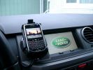
BlackBerry Tour 9630 mounted on air vent264 viewsThe antenna amplifier is mounted lower near the steering column. The amplifier box is painted black but looks sort of gold coloured due to the lighting in the other jpg showing the amp located under/near the steering column.
|
|
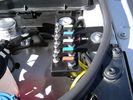
View of mounted panel from front left corner732 viewsI drilled a hole for the supplied 6 mm tie down toggle bolt in a flat portion of the wing on which the panel sits. I inserted a 50 mm flat rubber washer between the wing metal surface and the underside of the black painted panel plate; also a 40 mm flat rubber washer between the supplied fender washer and the metal plate - just seemed like a good idea so surfaces mate well even if wing metal not completely flat.
|
|
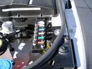
View from front left side looking towards rear aux battery compartment under cover 643 viewsAs there is no Fuel Burning Heater in the NAS V8 petrol vehicles, there is space available to install the FASKIT panel here. The piping is such that each air spring can be isolated from the air system and then filled one at a time manually via the Schrader valve. There are five Schrader valves and five shutoff valves. The fifth valve nearest the gauge controls air from the compressor, and can provide fill up air via a jumper fill line assuming the compressor is still operational.
|
|
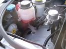
Empty space in NAS LR3 for location of FASKIT panel596 viewsThe empty space is available as the North America Spec gasoline engine LR3's do not have the Fuel Burning Heater installed. The air lines from the four air springs and the air tank will appear to rise up from under the headlight assembly. The lines to the front block valve assembly located behind the front right fog light will sort of run within the bumper across the front of the radiator down into behind the righthand fog light. The rear lines somewhat follow the path of the existing air feed line from the front valve assembly to compressor. Rather than be located between the left front fender liner and left metal wing however, the four lines will feed thru the empty wing space inside and above the wheel well arch and exit down by the left front mud flap. From there, the lines run along the left frame member above the air tank and then parallel the frame over top the compressor to the top of the rear left air spring where the rear air block valve assembly is located.
|
|
Dust Seal duct taped back together 2260 viewsThis shows the dust seal duct taped back together; also the surplus wire rope exiting from the actuator area prior to being cut to length.
I do not think the sticky plastic membrane is a dust seal, but more of a cable protector to cover up the wiring bundle that is effectively sticking to the underside of the flexible membrane.
|
|
Flexible wire rope fishing leader 0.032" diameter exiting carpet 1934 viewsThis is all you see of the completed mod.
The short little angled "line" about an inch long that looks like a piece of debris and is located a few inches "above" the support cable is actually the wire rope release cable exiting from under the carpeted lift gate cover.
I drilled a very small hole in the carpet and pushed the 0.032" diameter release wire thru and then slipped the loose end under the black plastic.
To release with the lift gate etc closed, from the inside, just pull the loose end free from under the black plastic and gently pull wire about 5mm, (1/4"), and the upper door catch should release. You will have to manually push the upper door out wards to actually effect opening, but you will already be inside the rear cargo area so that part is easy to do.
The assumption is that the lower door latch still works electrically and hence, the lower lift gate half will open as normal by pressing the usual button on the top left of the lower door half.
|
|

Carpet Panel Removed showing Bass Speaker and Dust Shield 1723 viewsSomething is wrong with the orientation, however this shows what you see when the carpet is removed.
The dust shield, (under which the actuator is located), in the picture is as yet uncut. The white bit is the underside of the plastic lower lift gate carpeted cover panel.
The round thing is the woofer speaker for the Harmon Kardon radio. When the radio is working, one can see the speaker moving, but not much bass sound actually seems to emanate from the speaker.
|
|
Carpeted cover removed showing uncut dust seal and underside of carpeted cover. 1618 viewsNote that there are all sorts of electrical wires sticking to the underside of the dust shield - so be very careful when you cut thru the shield.
I used a box knife very slowly and was surprised at how many conductors there were running just under the shield membrane.
|
|
Dust seal cut; note electrical conductors right under dust seal 1616 viewsShows what is underneath when the dust seal is cut. Note the electrical conductors.
I used a box knife to cut the plastic and it was at first easy; then I seemed to hit something and fortunately I stopped - it was the wires - lots of them stuck right to underside of the sticky seal material.
Also shown are the two 8mm nuts in slots that you only have to loosen to release the gold actuator assembly.
|
|
Dust seal rolled back showing electrical conductors 1647 viewsNote power conductors just under the dust seal which makes cutting the seal more interesting.
Also shown are the two 8mm nuts located in slots. One must loosen each nut to effect removal of the actuator. This will then reveal two T15 Torx screws that one must completely un-thread to remove the top gold plate from the actuator assembly.
|
|

NAS 7 Pin Round Socket + 4 Pin Flat Socket oriented as installed.742 viewsThis is the layout you see when you look into the NAS Land Rover sockets as installed at the rear of the LR3/4. The flat 4 pin socket is located under the round socket.
Wiring order is relative to the slot on the round socket, and hence the same as the other jpg where the slot is shown at the top.
The CJB monitors the front and rear turn signal lamps and can detect if more than four lamps are fitted, (the side turn signal lamps are not monitored). This is another reason for using genuine LR bulbs as off shore bulbs can have varied and out of spec resistance values.
When a trailer is detected, the trailer warning indicator in the instrument cluster is supposed to flash green in synchronization with the turn signal indicators.
If one or more of the turn signal lamps on the vehicle or the trailer are defective, the trailer warning indicator will cease to flash any longer. This is to alert the driver to probably bulb failure.
If the trailer has LED lamps installed, and no LED adapter circuitry is used, most likely the trailer will not be sensed and systems such as the backup sensors will not be disabled.
|
|

Wheel cut thru definitions and specs894 viewsNote the location of REAR SPACING and also OFFSET; probably two of the most important dimensions and not always understood as related to wheel size and relationship to the brake components.
For the 3, Rear Spacing is approximately 6.5 inches or 165 mm for a nominal 8" rim. Offset is 53P or 53mm Positive, which means the distance from the machined hub flat mounting surface to the rim's true centreline is 53 mm in the outboard direction. (The rim illustrated has a negative offset.)
As Positive offset increases, this means the wheel wraps around the disc brake mechanism more deeply, and hence the more the wheel would cover the brake parts. This is why most 18" wheels will not fit with the larger Brembo "supercharged engine" brake calipers.
Pitch circle diameter is 120mm; Pattern is 5 lug, and the tyre load rating is 112 with a recommended tyre speed rating of H or higher along with the XL load rating. For the 3, the stock tyre diameter is about 30 inches. The 255/60/18 or 255/55/19 OEM tyre outside diameter is 30.04 inches; Wheel lug torque is from 130 to 150 Nm or 96 to 110 lbf-ft and the lug nut hex socket size is 22mm.
Max Load High Speed Driving Tyre pressures are Front, 33 psig, (230 Kpa) and Rear, 42 psig, (290 Kpa).
The OEM rims are rated at 940 kgs, the highest that LR makes, hence while rims from other Land Rover products may physically fit, the odds are they are under rated in a weight sense.
|
|

Underhood Fuse and Relay Box drawing 3041 viewsShows the various fuse and relay locations. Fuse 3E, (5 amp), and Fuse 26E, (20 amp), as well as upgraded 70 amp Relay 7, part number YWB500220, locations are displayed. Relay 7 sends battery power to the compressor from the 60 amp fusible link called up as 10E. Fuse 26E is what provides full time always on battery power to the air suspension ECU and hence powers the auto level wakeup when the vehicle is shut down and say parked for the night. Removing F26E is the primary method to disable the air suspension system; Removing F35P is more if you want to experiment with it from inside.
I found it useful when I had a suspension problem, (actually a wheel alignment problem picked up by the steering wheel angle sensor), that only showed itself on the highway but allowed for no trouble light driving in the city. This was because in the city, the steering wheel was always in motion and rarely was the vehicle driven in a near straight line for very much distance.
|
|
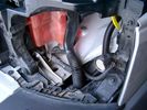
19 mm wire, (tubing), loom rising from below at left headlight654 viewsFrom the FASKIT panel, five air lines fit in the 3/4" (19mm) wiring loom and feed to the front air valve block located behind and under the right front fog light.
|
|
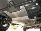
Rasta underbody protection plates446 views
|
|

LR3 Denso Alternator YLE500390 pulley view817 viewsNote the DENSO sticker on the side. Denso calls their nominal 150 amp 12 Volt alternator an SC2 design. SC means Segment Conductor which apparently increase the winding density of the stator coil, hence yielding a physically smaller lighter alternator for a given output. I presume the 2 means the second try at getting it right. A Denso part number is 4280003690 for the alternator, (there are others, as below).
Rotation is clockwise and the 54mm diameter pulley has 6 grooves (PV6x54). Count the pulley grooves on both the one you remove and your new one - some replacement alternators seem to ship with 5 or 7 grooves so you might be swapping pulleys.
A previous LR part number was YLE500190 for the older variation of the newer YLE500390 unit.
An additional part number for a factory rebuilt is Nippon Denso 210-0569 for the petrol V8 alternator. Other Nippon Denso numbers include 104210-3690 and 104210-3691. The Lester number is 11206 which relates to another Denso number of 290-5287. WAI uses 11206N.
From 2006 to 2009, the internal regulator is a Transpo IN6349 and of the B circuit type if it can be said that applies to PWM, (Pulse Width Modulated), regulators.
The "regulator" inside the alternator is therefore really not a regulator in the old sense of the term but instead an instruction receiver from the ECM that translates Pulse Width Modulated (PWM) signals into a form that the alternator understands – digital like signals from the Engine Control Module(ECM) into analogue like signals that the windings understand.
|
|

Power Door Lock Wiring689 viewsAbove is a 5 page, (pages 222 to 226), pdf wiring diagram for the power door locks for the LR3.
You can download and print as required. For on screen reading, use the right click rotate feature.
Additional pdf's regarding Locks can be found within the Gallery under the Power Windows and Door Lock Circuits heading.
|
|

Compare LR lettering101 viewsWhat happens when you let the dealer 'fix' the problem of deterioration of the bonnet badge lettering. Compare the left with the right side (LAND cf. ROVER). Only one side was 'fixed' under warranty.
|
|

Thread upload40 viewsImage uploaded in thread 134203
|
|
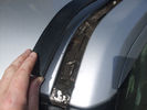
Mud under roofrail trim177 views
|
|
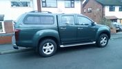
My Isuzu DMAX with Truckman Max Canopy25 viewsFinally got all the bits I paid for from the dealer - a Truckman Max Canopy and a spare wheel - unbelievably the default option on these is a can of foam and a compressor - thick end of £290 to get a full sized spare and the hoist to sling it underneath (much the same as a Disco, which means equally as stealable, might need to acquire a 17" spare protector of Uncle Ray)
|
|
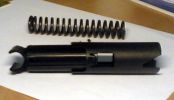
Mystery part that I found under drivers seat260 views
|
|

NAS 7 plus 4 pin LR3 Trailer wiring, battery end. 539 viewsThis is the LR wiring diagram from the engine compartment battery location to the Electric Brake Controller connector, C2590, located under the dash near the brake pedal.
|
|
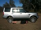
160 viewssuspension extension mode... 6\'3" son could have crawled under the vehicle easily.
|
|

9 views
|
|
Thread upload1 viewsImage uploaded in new thread
|
|
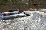
Thread upload18 viewsImage uploaded in thread 132198
|
|
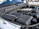
Overview of engine compartment from Main Battery side, (Passenger, LHD), looking across to Aux Battery749 viewsNote labels on main battery cover. The one you cannot read says that an auxiliary battery is installed on the other side. This is to warn service people should they wish to shut off all battery power.
The main starting battery is supposed to be of CaCa separator construction and DIN H8 or BCI Group 49 size. This means Calcium separators Wet Flooded Lead Acid, 13.9" long, 7.5" high and 6.9" wide.
On the Aux battery cover is a label saying to disconnect the blue Anderson single pole connector located under the cover by the brake reservoir. BCI Group 40R battery is small enough that the cover goes back on.
|
|
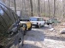
start of the day416 viewsVery nice selection of Rovers attended the trials. I had the only LR3. The had two classifications, short wheel base (under 100 inches) and Long Wheel base (over 100). LR3 was classified in the long.
|
|
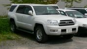
Toyota Hilux Surf182 viewsParked near the Imperial Palace Kyoto.
Kluger uses same underpinnings but Surf looks better.
|
|
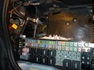
Battery Box Primary178 viewsThis visual is what is next to, behind and under your battery. It is important to note that the negative terminal which is prone to corrosion is in the rear, nearest to everything to maximize damage. The white powder pictured is baking soda. This is carefully used with a damp rag to neutralize any effect of battery acid (hydrochloric acid).
|
|

Ballina Motel Adornment112 viewsDidn't quite know what to make of this bit of ornament in motel at Ballina. However we were glad to listen to very heavy rain - shame I didn't want to take the car out from under cover to wash off the mud from the last week of 4WDing.
|
|

Unknown bird at sand pumping station near mouth of the Tweed River122 viewsNoisy little bugger who remained under walkway but eventually came out and then flew away flying low over water towards Tweed Heads.
|
|
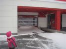
81 viewshave you ever seen so much snow under a roof?
|
|
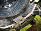
Underworld252 views
|
|
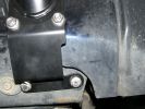
underside bracket (1 of 2) NS shown65 views
|
|

374 viewsSkiing under floodlights
|
|
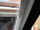
To remove a post trim insert small screwdriver under air bag logo, underneath is a torx screw353 views
|
|
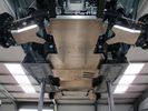
D3 and D4 Underbody Protection177 viewsIncludes:
Sump guard
Centre guard (transfer box, exhaust, fuel tank)
Rear diff guard
A-arm guards
|
|
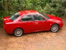
Alfa 156143 viewsOur 'other car' - not to be used on off road situations or 'She, who it is best to obey' gets mad at me. The evidence on the underbelly is a dead giveaway.
|
|
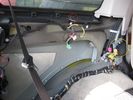
red is PDC sounder ...Yellow is PDC module 341 views
|
|
266 viewsthe repair involved stitching the loom together under the wing. i would have ordered a new one as they are not too expensive but colid not wait the 9 weeks delivery time so i used the front end of a loom from a breaker
|
|

door card under (rear)70 views
|
|
212 viewsUnder Cover when Garage full.
|
|
interface unit sat on dvd - cables pulled under seat frame408 views
|
|
12volt power from reverse light plus Video cable routed to from rear to under seat335 views
|
|
12volt power from reverse light plus Video cable routed to from rear to under seat319 views
|
|
12volt power from reverse light plus Video cable routed to from rear to under seat312 views
|
|
no need to remove this trim - cables easily go underneath them323 views
|
|

Complete underbody protection system photo render172 views
|
|

Complete underbody protection system117 views
|
|
Thread upload2 viewsImage uploaded in new thread
|
|

15 views
|
|

Thread upload2 viewsImage uploaded in new thread
|
|
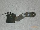
Radio Noise Suppression Capacitor NNW502820695 viewsThis is the radio noise suppression capacitor, part number LR020488 (previous NNW502820), that is mounted underneath and near the transmission. It is powered by fuse 10 amp F30E in the engine compartment. If F30E blows, (the fuse that also powers the transmission ECU), the problem is probably caused by the failed capacitor, not the ECU. A quick fix is just to disconnect the capacitor and replace the fuse as nothing bad seems to immediately result.
The above radio noise capacitor is not to be confused with LR004160, the ignition noise capacitor which is located under the black plastic engine cover on the right hand side above the air intake towards the rear of the engine.
The ignition capacitor is held on with a single 8mm bolt and a three wire electrical connector. Replacing the ignition capacitor as a routine maintenance prevention action at 100,000 miles, 160,000 km), has merit. It is a do it yourself kind of thing and easier to get at than the radio capacitor underneath.
|
|

Thread upload5 viewsImage uploaded in thread 159579
|
|
New Chassis placed underneath51 views
|
|

A flooded Lake Eyre74 viewsThisk salt crust forms but underneath is a thick black mud. Drive on this and its goodbye D3
|
|

Dinner under the stars105 viewsJonesy and WayneD\'s brother in law prepare to enjoy chicked and fried rice and the odd wine
|
|
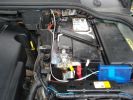
148 viewsI routed the white signal wire from the junction box which I positioned at the side of the battery, back and under the bonnet seal.
|
|
Thread upload4 viewsImage uploaded in thread 193079
|
|
Thread upload1 viewsImage uploaded in new thread
|
|

undergorund 2127 views
|
|

underground 1126 views
|
|
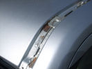
Rust under roofrail trim146 views
|
|
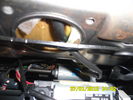
Wiring heated seat70 viewsThis picture is taking from behind the driver seat underneath.. the black cable that goes up in the hole is the wiring for the heat elements. There is a connector on the other end, not visible in this pic.
|
|
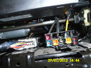
96 viewsConnectors under my driver seat..
Right connector for Heated seat + airbag ++
Left connector for Seat controll I hink
|
|
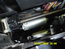
74 viewsUnder seat
|
|
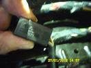
Heat connector76 viewsThis I found under the Dreaver seat. The connector says Ford Tyco This is for the heat element and the sensor I do beleave
|
|
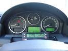
ScanGauge II on steering column of LR3797 viewsMAP is Manifold Absolute Pressure, what I call Vacuum.
The volts is I think the battery charging voltage as it moves around from about 12.4 when shut down to 13.5 when the batteries seems charged; 14.9 is about as high as I have seen it display.
You also have RPM, speed in MPH or KPH, coolant temperature and a bunch of other readings including sort of instantaneous fuel in a variety of units.
Also under some conditions, the ScanGauge will reset the MIL light as well. The background colour of the display can be changed to many different colours. I have it set to match the LR green.
|
|
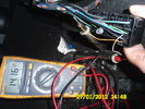
multiplugg under driver seat60 viewsThis picture is takin when diagnosing the heated seat element.
This show that there is 14volts to the elements on these wires.
|
|

124 views
|
|

Patch Antenna mounted to underside of glass roof at rear.193 views
|
|
Sounder Module fixed to body panel within LHS cubby hole195 views
|
|

51 views
|
|

Superinjunction85 viewsBefore Ryan Giggs was exposed as the two faced, nice as pie in public yet screwing any that moves behind closed doors hypocrite he is it was public knowledge that the woman in the story was some slapper from Big Brother but the footballer could not be named. Here we see TNT magazine's top story about her saying the footballer can't be named. Directly underneath is a link to a "related story" was a link to "Ryan Giggs, wife and kids celebrate Manchester United victory"
|
|
4x4 channel video switch (low) + alpine 425i on top left134 viewsmy car is 5 seater, so there is room under the seats...
|
|
18 views
|
|
373 views
|
|
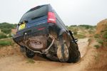
456 views
|
|
Thread upload27 viewsImage uploaded in thread 92518
|
|

Thunderbird 360 views
|
|
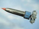
Thunderbird 168 views
|
|

Thunderbird 273 views
|
|

199 views
|
|

Thread upload7 viewsImage uploaded in thread 153697
|
|

3 views
|
|

Thread upload10 viewsImage uploaded in new thread
|
|

This is a picture of some peoples cars due to being lied to by people who do not understand what they are doing..40 viewsThis is a picture of some peoples cars due to being lied to by people who do not understand what they are doing.
|
|

Towing outfit200 viewsTowing our Trailcraft 5.4m "Panorama Dirt Road" caravan (March 2008).
Heavy duty springs and 150mm hitch riser on LR "plough" has made the outfit level. There's a slight nose-up attitude and some pitching front and back whilst under-way. We're looking forward to taking delivery of a Mitchell Bros towbar so that we can use our Hayman Reece weight distribution hitch (which will correct the nose-up and reduce the front-back pitch).
|
|

Armed Forces Land Rover on Trackrod Rally 201138 viewsMatt O'Hare & James Sunderland in a Land Rover Wolf on the 2011 Trackrod Rally
|
|
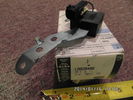
Radio Noise Filter Transmission Electronic Control Unit898 viewsThe jpg shows part number LR020488, a noise suppression capacitor located underneath on a bracket on the right side of the transmission forward of the selector shaft lever. The suppressor is connected to the transmission wiring harness and prevents solenoid operating noise affecting the audio system.
Failure of the capacitor is most often discovered as a result of either black smoke from below and or the blowing of 10 amp fuse F30E located in the engine compartment fuse box. This fuse protects the power circuit to the Transmission Engine Control Unit. When the fuse blows, the engine will still run however you have no gears, hence movement of the 3 is inhibited.
Anything over eight years in service is considered good capacitor life. If the capacitor does fail and fuse 30 blows, a quick fix is just to disconnect the capacitor and replace the fuse.
The capacitor might be missed by the DOT/FCC but the 3 does not seem to mind. With the filter disconnected, solenoid noise might be heard on some radio stations but at least the 3 would be in motion.
|
|
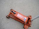
Trolley Jack Adapter817 viewsThis shows my 2.5 long ton, (2,540 kg, 5,600 pounds), trolley jack with the pin adapter that slots up into the round holes on the underside of the frame.
Use of the adapter when lifting by the left rear wheel ensures that I will not be jacking on the air compressor support; on the other three corners, it is much safer than merely jacking directly on the nearly flat narrow underside of the frame rail.
|
|

First bit of Sand under foot/tyre :-)121 views
|
|

D3 and D4 Underbody Protection162 views
|
|

D3 and D4 Underbody Protection166 views
|
|
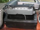
View from underneath96 views
|
|

11 views
|
|
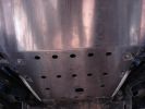
From Discotr.es89 views
|
|

9 views
|
|
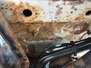
Thread upload9 viewsImage uploaded in thread 188404
|
|
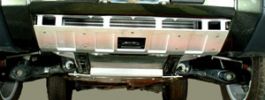
165 views
|
|
84 views
|
|
80 views
|
|
76 views
|
|
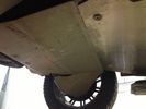
79 views
|
|
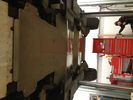
87 views
|
|
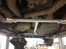
97 views
|
|

Undercover D429 views
|
|
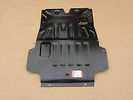
Thread upload11 viewsImage uploaded in new thread
|
|

under the seat45 views
|
|
Thread upload2 viewsImage uploaded in new thread
|
|

Undershield Fitment201 views
|
|
34 views
|
|
Thread upload1 viewsImage uploaded in thread 207823
|
|
Thread upload2 viewsImage uploaded in thread 207823
|
|
Thread upload1 viewsImage uploaded in thread 207823
|
|

17 views
|
|
401 views
|
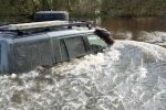
|

16 views
|
|
171 views
|
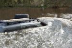
|

Thread upload2 viewsImage uploaded in thread 159579
|
|

LOCK ME UP!!180 views
|
|

omg214 views
|
|
73 views
|
|
0 views
|
|
1 views
|
|
Thread upload1 viewsImage uploaded in thread 156265
|
|

Thread upload12 viewsImage uploaded in new thread
|
|

Thread upload17 viewsImage uploaded in thread 1189
|
|

Vehicle Maintenance Log for LR3/4 D3/4 or other1127 viewsThis is a Excel file that you can download and then modify to suit. It is very simple, but allows me to keep track of most maintenance and fixes etc on my LR3. All columns and rows and boxes can be edited.
I did not erase any data in the various boxes so you could see how I am using it - again not very fancy but it works for me. Under the brakes column, one will see f6 r5 which is how I keep track of the condition of the brake pads. The dealer records the pad thickness at each oil change so that is where the numbers come from.
f is for Front Pads, 6 is for 6mm; r is for Rear pads, 5 is for 5 mm. New pads are about 10 mm; replacement is at 3 mm or less. The amber coloured brake wear dash warning light should come on at about 2 mm.
|
|
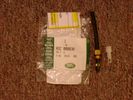
Voss System 203 connector 6 mm for valve blocks 900 viewsThis is Land Rover part number RQC000030, the Voss fitting for the axle valve blocks. I think it is a Voss System 203 6mm fitting, Voss part number 5 2 03 11 01 00.
The parts bag comes with the white plug inserted in the brass threaded bit with what is called the brass cutting ring placed on the tip of the white plastic plug. The idea is that one screws, (M10 x 1 thread), the brass insert into the appropriate hole with the white plug still in the brass insert. Once the brass is tight, (12 mm wrench), then the white plug is pulled from the assembly leaving the cutting ring down inside and under. One then pushes in the 6 mm tube end about 20 mm or so and the tube slides down thru the brass cutting ring, (2 internal sloped one way cutting ridges). When the tube is in far enough, one pulls upwards a bit and the ring cuts into the plastic such that the tube will not pull out. To remove tube, one unscrews the brass nut and all comes out, sort of like I have shown with the short piece of 6mm tubing. The white plug is a throwaway item upon install of the tubing.
|
|

Dune Descent91 viewsNo picture seems to do sand dunes justice in terms of their scale and beauty. This was a 100 metre dune (according to the GPS track profile anyway)in the driest, softest sand that behaved like a liquid as you descend the slope. Low 1st, DSC and HDC off and feathering the throttle was the technique used and the descent happens under full control.
|
|
Amdeal 30ft / 10M USB Digital Microscope Cable Wire Endoscope Camera Video Recording Inspection Pipe Camera - Waterproof, 4 LED Lights23 viewsUnder XP system, can watch video directly without install software. By using our software, can take photo,record video, and save the video in the PC. Such USB microscope widely used to inspect tube, check the body, magnify stamps, coins, antiques, insects, electric circuits, machines, fabrics, food, decorations, etc. Please notice that the wire camera is designed for industrial use, not for medical use.
Camera: 1/6" VGA COMS
Pixel: VGA 300K
Resolution: 640x480,352X288,320X240,176X144,160X120
Capture Resolu
|
|
DiscoDunc going undercover146 views
|
|

105 views
|
|

ZF LifeguardFluid6 transmission oil.1388 viewsThis is an interesting pdf in that under the ZF 6HP26 six speed section, it provides the various automobile manufacturer part numbers for their version of the appropriate tranny oil, all of which seems to be the LifeguardFluid6 oil, ZF part number S671 090 255. Note the fine print and do not confuse it with the LifeguardFluid6 Plus oil for vehicles with the Torsen AWD setup such as the Audi Quattro, VW 4Motion vehicles and I think the BMW FF Range Rovers of an earlier time.
Also of interest at the bottom of the pdf is the recommendation for replacing the transmission oil "between 80,000 km and 120,000 km or 8 years, depending on the load." I also do not see any reference to "sealed for life" but almost as optimistic, "maintenance free" but with the proviso "intended for normal operating conditions". This would most typically be the Sandringham Castle Grounds in the UK rather than Cape York, QLD.
|
|

Underside of ZF 6HP19 and 26 transmissions pans1417 viewsThis is a view of the underside of two different plastic transmission pans, one for the ZF 6HP19, and the other, the 6HP26.
The 24 Torx screw pan is for the 6HP19; the 21 Torx screw pan is for the 6HP26/28/32 transmissions. The screws are numbered in the order that they are to be tightened re the O ring seal. Our 3 has the 21 screw transmission, the ZF 6HP26X six speed.
|
|
|
|