NAS Trailer Socket Pin ID and Wire Colours |
 |
| TITLE |
+ |
- |
| FILE NAME |
+ |
- |
| DATE |
+ |
- |
| POSITION |
+ |
- |
|
|

Tekonsha P3 Electric Trailer Brake Controller model 90195281 viewsOne model of electric brake controller that is commonly used on the LR3 is the Tekonsha P3 unit, model number 90195. It mates up to the LR3 with a custom "Ford" adapter cable, Tekonsha part number 3035P. No wire cutting or splicing is necessary - just mount unit and plug adapter cable in.
|
|

Tekonsha P3 Brake Controller 90195 to Ford 3035-P wiring adapter plug306 viewsThis two page pdf is the general instruction for hooking up the Tekonsha part number 3035-P adapter cable between a Tekonsha P3 controller and the existing Land Rover/Ford plug, (called C2590 in the Land Rover wiring diagrams), that is hidden above the brake pedal.
The "Ford" plug, (C2590), is grey and is stuffed up above the brake pedal arm.
Mount the P3 controller appropriately and then connect one end of the custom cable to the P3 and the other to the "hidden" plug.
You will now have power for your trailer electric brakes in the round socket at the rear of your LR3; also no computer update from the Land Rover T4 unit is required. For once, it is plug and play.
If however, your trailer has LED tail lights, you may have trouble with the flashing of the trailer signal lights or non recognition by the 3 that a trailer is connected. As such, the little green trailer signal will not illuminate when a trailer is connected and the signal lights are used. This can affect the shifting of the transmission and much to your annoyance, the backup sensors will still be functioning rather than being auto disabled.
|
|

Tekonsha Ford Brake Controller Adapter part number 3035-P270 viewsThis is the adapter cable between the Brake Controller and the existing C2590 female plug located near the brake pedal on NAS spec LR3's. The flat 4 pin plug of the adapter cable connects to the Controller; the rectangular 6 hole male plug to C2590.
There are only four conductors in the adapter cable, but one will see five pins within the Land Rover C2590 plug. The #2 pin is not required for the NAS setup. #2 pin is the circuit between the head lamp switch and vehicle side running lamps required in the civilized world.
The single pin at the bottom in the picture is #3 and on the Land Rover, a Black wire tied to ground. The other pin at the bottom and across to the left is #6, and Blue on the Land Rover. This is the Brake Controller output to the trailer socket at the rear.
#4 is the pin at the top left, and is a White coloured wire from the battery. Pin #5 is from the stop light switch, and is Green on the Land Rover.
Note that the adapter cable colours do not necessarily follow all the above referenced Land Rover colours.
|
|
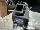
Rhino Tow Loop Hitch263 viewsThis is a receiver end view of the Rhino Hitch that ties to the factory tow loop. In addition to improved strength, it does not reduce ground clearance as does the factory style when installed.
Land Rover in early advertising videos when the 3 first came out showed the D3 hanging from a crane via the frame. The intent was to show how strong the frame is and by inference, the rear tow loop, specifically noted as being good for 6 tonne. The video ends before anything dropped or was lowered back to the ground, so one of course does not know for certain. The Rhino Hitch design however picks up on the apparent evidence of strength and certainly the additional clearance.
|
|

NAS Trailer Wiring Colour Code356 viewsThis is a common wiring colour code for trailer wiring in North America. Some vehicle manufacturers follow the code for at least some of the functions.
|
|

NAS 7 plus 4 pin LR3 Trailer wiring, trailer end. 490 viewsThis is the LR wiring diagram showing the conductors from the the Trailer Brake Controller connector, C2590, back to the rear combo NAS 7 plus 4 pin sockets.
|
|

NAS 7 plus 4 pin LR3 Trailer wiring, battery end. 539 viewsThis is the LR wiring diagram from the engine compartment battery location to the Electric Brake Controller connector, C2590, located under the dash near the brake pedal.
|
|

NAS 7 Pin Round Socket + 4 Pin Flat Socket oriented as installed.742 viewsThis is the layout you see when you look into the NAS Land Rover sockets as installed at the rear of the LR3/4. The flat 4 pin socket is located under the round socket.
Wiring order is relative to the slot on the round socket, and hence the same as the other jpg where the slot is shown at the top.
The CJB monitors the front and rear turn signal lamps and can detect if more than four lamps are fitted, (the side turn signal lamps are not monitored). This is another reason for using genuine LR bulbs as off shore bulbs can have varied and out of spec resistance values.
When a trailer is detected, the trailer warning indicator in the instrument cluster is supposed to flash green in synchronization with the turn signal indicators.
If one or more of the turn signal lamps on the vehicle or the trailer are defective, the trailer warning indicator will cease to flash any longer. This is to alert the driver to probably bulb failure.
If the trailer has LED lamps installed, and no LED adapter circuitry is used, most likely the trailer will not be sensed and systems such as the backup sensors will not be disabled.
|
|
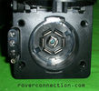
NAS 7 pin + NAS 4 pin Flat Trailer Socket304 viewsThis is the vehicle end of the NAS trailer harness that is located behind the removable plate centered within the rear bumper by the towing loop. Re the four pin flat connector, from the bottom, the exposed bare lower pin is the ground, usually the White wire on a NAS trailer. The next pin up is normally a Brown wire on a trailer and is for the Tail Lights. The third pin, normally a Yellow wire, is the left signal light; the top pin, normally a Green coloured wire, is the right signal light.
Re the round connector, from the notch in the plastic surround, clockwise, the first blade is ignition controlled +12VDC battery power, (only alive when engine running), and on the Land Rover factory harness is an Orange wire; on a NAS trailer, usually Red but perhaps a Black wire.
Next blade clockwise at 3:00 o'clock above, is the Right Turn signal light, a Green wire on the LR harness, and also on a NAS trailer.
At 5:00 o'clock, the next blade is for the Electric Brakes and is Blue on both the LR harness and on a NAS trailer.
The Ground wire is next, White on both the LR harness and on a trailer.
At 9:00 o'clock above, is the Left Turn signal, Yellow on both the LR harness and on a trailer.
The last blade to the left of the line up notch is the Tail Light circuit. On the LR harness, the wire colour is Brown with two White stripes and on a NAS trailer, Brown.
The centre pin is for the Reverse Back Up lights and is Black on the LR harness and often Purple on NAS trailer wiring but can be Black also.
Note that when the socket assembly is installed on the 3, the notch in the plastic surround is on the left - that is rotated 90 degrees anticlockwise to the picture above. In other words, When installed on the 3, the 4 pin flat connector lays horizontal and is located below the round socket.
|
|

NAS 7 Blade Round plus NAS 4 Pin Flat Vehicle end Socket522 viewsThis shows the function of each blade when looking into the connector at the vehicle end for the 7 pin NAS plug. The layout is the pin order for most new North American pickup trucks and the LR3/4.
The colour and gauge of the wires feeding into the back of the plug varies even within manufacturer model lines.
Also detailed is the flat 4 pin layout common on smaller trailers not having electric brakes. This includes most U-Haul rental trailers.
|
|
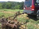
LR3 to plow your garden289 viewsI found this jpg where a current LR owner is using his LR3 for a similar purpose as the original Series units were designed to do - that is serve as a tractor for plowing a field or I suppose a garden.
In this case, I note the hitch is one of those that attach to the factory tow loop, (Rhino Hitch), rather than the factory product that inserts from the bottom and hangs down - (like a plow), but all the time. One of the other jpg's in this album shows the two factory variations plus a third jpg shows a closeup of the Rhino Hitch.
|
|

LR3 and 4 NAS hitch receiver original and newer third generation.767 viewsThe picture shows the original 2005 model "plow" for the LR3 and the newer shorter hitch receiver introduced with the LR4. Either receiver can be used on the LR3/D3; they are interchangeable.
The part number of the newer third generation short style is LR019990 replacing previous long type part number KNB500080. There were two versions of the longer one, KNB500080 with the orange key, apparently a better locking setup. The first generation, KNB500023, with a black key was less than perfection.
The green lock assembly with orange key, part number KNW500010, shown on the shorter hitch, can be purchased separately should a key be lost.
Regardless of receiver model, the receiver will accept nominal NAS 2" tongue on which may be mounted the appropriate ball size.
|
|

LR Electric Trailer Brake C2590 Female Connector598 viewsThis female connector, C2590, located up above and near the brake pedal is for the Trailer Electric Brake Controller hookup.
The Black wire in the bottom right is pin #3, the ground. The Blue wire to the left is pin #6, the Trailer Brake Controller output going to the rear trailer socket.
The White #4 wire is the 30 amp fusible link, (Link 6E in the engine compartment junction box), for the Brake Controller 12VDC power feed from the battery. Note that this would make a pretty good power source for CB radios and the like if no electric trailer brakes were required.
Pin #5 is a Green wire from the stop lamp switch, (the control input for the Brake Controller).
This plug is standard on all NAS (LR3) vehicles, but unlikely to be found on the D3 spec units.
|
|

LED trailer lights adapter for LR3831 viewsThis doc includes a partial list of materials and the instructions/links required to construct an adapter to prevent LED trailer lights from pulsing due to the 3's diagnostic circuits interrogating the signal light circuit.
Using the adapter also facilitates the green flashing of the dash located trailer indicator when the signal lights operate plus inhibits operation of various systems such as the backup sensors, etc.
|
|

Harness that connects inside left rear compartment.435 viewsThis is the harness section that connects behind the left rear interior access panel and exits thru the large grommeted hole to below/behind the left rear tail light.
Note the two rubber grommets on the harness as there is both an interior metal skin and an exterior metal skin behind the left tail light assembly.
The two light grey connectors plug into two existing connectors near the top of the rear left interior access panel. The two darker connectors plug into the second piece of harness.
There is no little separate fuse box either with the NAS spec harness. The fuse box is included with the UK 13 pin dual plug units. If there was a fuse box, it would be on this portion of the harness.
|
|
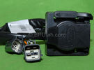
Harness section that runs behind the rear bumper.405 viewsThis is the harness section that clips up inside the rear bumper and includes the circular 7 pin, (6 flat +1 round), NAS socket, and also the 4 pin NAS flat connector.
The two small plug ends connect under the rear left tail light to the harness section that exits from the interior.
The Land Rover part number for the NAS trailer tow kit, (both cables), is YWJ500220.
|
|

Curt Manufacturing Installation instructions Class III339 viewsThese are the instructions for installation of the Curt Hitch.
|
|
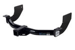
Curt Manufacturing brand hitch, assembled but not installed.282 viewsThe Curt Manufacturing hitch is an alternate to the Land Rover removable "plow" hitch. Once bolted in place, the Curt hitch is always there.
The Curt part number is 13456. It is a Class III hitch with a 2" square receiver and designed for a maximum 600 pound tongue weight.
The hitch hangs below the rear bumper but does not stick out past the bumper; also the "donut" spare tyre can still be installed / removed; am not so certain about a full sized fully inflated spare.
|
|
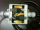
Box open showing Hella Relays and Putco Load Resistors732 viewsInterior of the box - note the two gold coloured 6 ohm 50 watt load resistors are a bit distant from the other items so as to provide some separation for dissipation of the heat generated.
Rather than a moulded plastic weather resistant box which I would have preferred, I used a bulky and much heavier metal weather tight style electrical box so the metal can act as a heat sink.
|
|
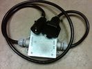
Box Closed with 7 Blade NAS connectors576 viewsBox closed up and ready for use. The box and cable connectors are reasonably weather tight and hence can be submerged for a bit while doing a creek crossing but as with the 3, do not use the creek bed as a parking stall. Similarly, the connector recessed into the bumper will probably remain somewhat dry as long as you keep moving but if you get stopped, well that is another story.
As such, I put a vial of desiccant in the metal box prior to closing it up to reduce corrosion due to moisture build up.
|
|
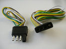
4 pin NAS flat connector from NAS small trailer377 viewsThe connector with the three exposed pins is the end that would commonly be located at the trailer hitch end, (front), of a small NAS lightweight trailer that has no electric brakes. This plug would connect into the flat 4 pin connector at the rear of the 3.
Note the order of the pin functions and wire colours: White is ground; the next pin is for tail/marker lights using the Brown wire; the Yellow conductor is for the left turn signal, and the far pin uses the Green conductor for the right turn signal.
There is no separate brake light conductor as NAS spec vehicles most often combine the brake and signal light functions to the same bulb filament rather separate filaments in different bulbs. The LR factory harness resolves that design difference.
Fortunately, the Land Rover NAS assembly pin order for the 4 pin flat plug maintains the above described conventions.
|
|

3 Point Hitch on Series 90148 viewsUsually one sees the Series units with just a conventional field plow hooked to a drawbar hitch, tractor style. This jpg however is the full meal deal - a 3 point hitch, probably off a Fordson tractor, in the long tradition of Ford/Land Rover cooperation.
|
|
|
|
|
|