| Last additions - nessie's Gallery |
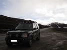
Thread upload11 viewsImage uploaded in thread 15881026 Apr 2017
|
|

11 views22 Apr 2017
|
|
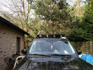
10 views22 Apr 2017
|
|
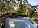
8 views22 Apr 2017
|
|
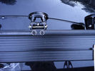
7 views22 Apr 2017
|
|

9 views22 Apr 2017
|
|

9 views22 Apr 2017
|
|
8 views22 Apr 2017
|
|

5 views22 Apr 2017
|
|
2 views22 Apr 2017
|
|
2 views22 Apr 2017
|
|

2 views22 Apr 2017
|
|

2 views22 Apr 2017
|
|

2 views22 Apr 2017
|
|

1 views22 Apr 2017
|
|
1 views22 Apr 2017
|
|
1 views22 Apr 2017
|
|
2 views22 Apr 2017
|
|

2 views22 Apr 2017
|
|

1 views22 Apr 2017
|
|

1 views22 Apr 2017
|
|
1 views22 Apr 2017
|
|
1 views22 Apr 2017
|
|
1 views22 Apr 2017
|
|

1 views22 Apr 2017
|
|

1 views22 Apr 2017
|
|
1 views14 Apr 2017
|
|

2 views14 Apr 2017
|
|
2 views14 Apr 2017
|
|

2 views14 Apr 2017
|
|

1 views13 Apr 2017
|
|

1 views13 Apr 2017
|
|

1 views13 Apr 2017
|
|
1 views09 Apr 2017
|
|
2 views09 Apr 2017
|
|
2 views09 Apr 2017
|
|

2 views09 Apr 2017
|
|
2 views09 Apr 2017
|
|

2 views09 Apr 2017
|
|
2 views09 Apr 2017
|
|
3 views09 Apr 2017
|
|
2 views09 Apr 2017
|
|

2 views09 Apr 2017
|
|
3 views09 Apr 2017
|
|

2 views07 Apr 2017
|
|
1 views07 Apr 2017
|
|

2 views07 Apr 2017
|
|

1 views07 Apr 2017
|
|

1 views07 Apr 2017
|
|

1 views07 Apr 2017
|
|

1 views07 Apr 2017
|
|

1 views07 Apr 2017
|
|
4 views07 Apr 2017
|
|

3 views07 Apr 2017
|
|
4 views07 Apr 2017
|
|

1 views05 Apr 2017
|
|

1 views05 Apr 2017
|
|

1 views05 Apr 2017
|
|

1 views05 Apr 2017
|
|

1 views05 Apr 2017
|
|

1 views05 Apr 2017
|
|

1 views05 Apr 2017
|
|

1 views05 Apr 2017
|
|
1 views05 Apr 2017
|
|
1 views05 Apr 2017
|
|
1 views05 Apr 2017
|
|

1 views04 Apr 2017
|
|
2 views04 Apr 2017
|
|
1 views04 Apr 2017
|
|

1 views04 Apr 2017
|
|

2 views04 Apr 2017
|
|
2 views04 Apr 2017
|
|
1 views04 Apr 2017
|
|

2 views04 Apr 2017
|
|

1 views04 Apr 2017
|
|

2 views04 Apr 2017
|
|

2 views04 Apr 2017
|
|

1 views04 Apr 2017
|
|

4 views22 Mar 2017
|
|

1 views22 Mar 2017
|
|
3 views22 Mar 2017
|
|

1 views22 Mar 2017
|
|
2 views22 Mar 2017
|
|

3 views09 Feb 2017
|
|

3 views09 Feb 2017
|
|
3 views09 Feb 2017
|
|
2 views09 Feb 2017
|
|

Frontrunner Sump Guard Fitted9 viewsSGLD009
https://www.frontrunneroutfitters.com/en/be/protection-equipment/under-vehicle-protection/land-rover-discovery-2014-present-sump-guard-4-5mm-3cr12-stainless-steel-front-runner.html
04 Feb 2017
|
|
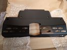
Frontrunner Sump Guard6 viewsFrontrunner Sump Guard unpacked29 Jan 2017
|
|

Thread upload5 viewsImage uploaded in new thread16 Jan 2017
|
|
Thread upload3 viewsImage uploaded in new thread16 Jan 2017
|
|
Thread upload6 viewsImage uploaded in new thread30 Dec 2016
|
|

Thread upload4 viewsImage uploaded in new thread04 Nov 2016
|
|

Thread upload2 viewsImage uploaded in new thread04 Nov 2016
|
|
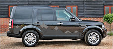
Thread upload6 viewsImage uploaded in new thread03 Nov 2016
|
|

Thread upload2 viewsImage uploaded in thread 15171423 Oct 2016
|
|

An extra twist on running lights28 viewsAdded those nice 120mm LED rings on the covers of the roofrack lights and have them connected to my roofrack lights switch, as I wanted to control the LED manually as well (I don't believe this is 'road-legal', hence why I opted for the manual solution).27 Aug 2013
|
|
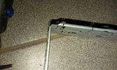
45 viewsI still needed to cut some small bits away from the DIN in order to have the facia cover fit nicely.20 Jul 2013
|
|
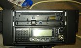
72 viewsThe Pioneer DEH X9500BT on top with the CB President Johnson II beneath.
I had to cut the bottom part of the CB 2 DIN conversion kit in order to have the supplied cover with the facia in place as it should.
I eventually didn't use the supplied facia of the radio as it's bottom part was covered by the CB's kit.20 Jul 2013
|
|

60 viewsFinal setup, everything in place after about one full day of work, which included removing quite some bits I had installed before.20 Jul 2013
|
|

60 viewsNormal usage, only the radio's on and controlling the connected iPod.20 Jul 2013
|
|

66 viewsRadio and CB activated. Tried to have the radio's colour similar to the CB.20 Jul 2013
|
|
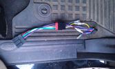
56 viewsThe OEM 2 ISO harness. Notice the red and yellow, which are important for my radio. Not having the red connected simply didn't activate the radio (so I wonder what the radio does with the permanent 12V)20 Jul 2013
|
|

64 viewsAdded a lead coming from the 12V outlet in the front console. That one is activated only when the ignition is set to I. So that's actually what is referred to as accessories in the manual of the radio. The OEM connector for the head unit did not have any similar lead. The yellow is permanent 12V, the red (on the converting OEM 2 ISO) is the accessories 12V.20 Jul 2013
|
|

33 viewsThe facia had some bits sticking out which fit quite nicely with the supplied double DIN support. As I was going to use the DIN supports supplied with either the radio and the CB, I needed to remove those bits sticking out. They made the DIN support bend as well.20 Jul 2013
|
|
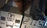
34 viewsWhen adding two single DIN supports together, you get quite a gap at the front.
This gap was way too much in my case, as it turned out that both supports started to bend when putting them both in the facia. Not that good, so I decided to cut off the upper part of the lower DIN support.20 Jul 2013
|
|
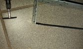
33 viewsThe result after the dremel hit the DIN support20 Jul 2013
|
|
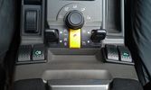
The on/off switch for the compressor11 viewsThe rocker switch for the compressor is the outer right one with the label of the .. euh, compressor :D14 Jul 2013
|
|
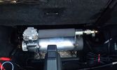
The compressor in the booth16 viewsThe rear of the second row seats are visible and the space behind was big enough to put the compressor.
The compressor is powered from the rocker switch in the front.14 Jul 2013
|
|
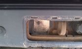
Outside connection to the compressor14 viewsFrom the compressor which is in the booth, the air hose runs to the back of the car.
I was able to install the connector in the space of the second trailer plug (which wasn't installed anyway).14 Jul 2013
|
|

President Johnson II in its current position16 viewsThis CB was installed some years ago and still is at the same location.
However, I'm planning to move it to the head unit area.
As such, I'm looking around to replace my low end head unit with a single DIN radio and the CB on top of it.14 Jul 2013
|
|
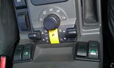
The on/off switch for the battery display20 viewsThe right inner switch 'powers' the auxiliary battery display. I might use that one to power on/off the driving camera (which will be arriving soon) as well. Although I'm not sure yet.14 Jul 2013
|
|
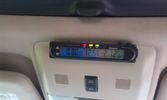
Battery check display14 viewsI mounted a digital battery display in order to see the voltage on the auxiliary battery.
There's also a thermometer which gives the inner and outer (via a side switch) values.
The display is switched on/off via another rocker switch.14 Jul 2013
|
|

The on/off switch for the middle outlet8 viewsThe left switch without the label is the one that now controls the middle 12V outlet on the second row. It used to be the power on/off of the car-computer.14 Jul 2013
|
|
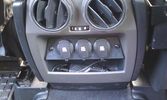
12V outlets for the 2nd row13 viewsI used a part of the old front (which was broke) to cut out a 'mount' for three 12V outlets for the second row.
The outer outlets are switched on whenever the ignition is on as I used the connector that originally was out there.
The middle outlet is connected to the auxiliary battery and is switched on/off through a rocker switch in the central console. (other picture)
This middle one is going to be used for our small fridge that usually resides just there when we're on holiday.14 Jul 2013
|
|
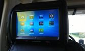
One of the multimedia headrests12 viewsI used to have seperate touchscreens mounted on the headrests.
I now went to the xtrons 9" headrests which gives the children the possibility to
- view whatever movie they want to
- listen to whatever music they want to
- play whatever 32native game they want to (although I'm not quite happy with those)
and they can do this no matter what the other one is doing :)14 Jul 2013
|
|
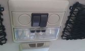
The on/off switches of the multimedia headrests14 viewsThese switches were installed to power on/off the previously installed gamecube and the screens attached to it.
When I removed the gamecube and lately the screens as well, I was clever enough (surprised as well) to leave the switches and all the wiring that I had running around.
They came in handy when I installed the multimedia headrests and are now adding an extra power on/off control of the screens.14 Jul 2013
|
|

An extra 12V outlet14 viewsOn the passenger side, I added a 12V outlet which is fed through the fuse box in the rear and adds as such an outlet for whatever charger we don't want to have lingering around around the central console.
The USB charging outlets are visible as well :)14 Jul 2013
|
|
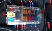
Fuse box in the rear12 viewsI installed the fuse box in the rear. Since I do have a 5-seater, there's plenty of space in the booth beneath the 2nd cover, which rests behind the second row seats.14 Jul 2013
|
|

Close up - key in place16 viewsThe key placed and turned in order to turn the switch on.
Everything connected to the fuse box in the rear and the fog lights on the roofrack will work now.14 Jul 2013
|
|
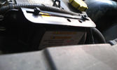
Solenoid not yet engaged12 viewsWith the engine running, the counter in the solenoid starts running and the green light blinks until the timer hits 5 minutes.14 Jul 2013
|
|
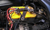
The auxiliary battery21 viewsThe auxiliary battery in the bay.
As the wiring diagram I made shows, there's a wire leading to the fuse box in the rear. (is going through the key-switch)
The second one is going to the fog lights. The smaller cables which should be connected to the head-lights, are connected to the battery.
The third one is going to the compressor (via a switch) (sits before the key-switch)
A fourth one is going to the CB and battery check display (sits before the key-switch)14 Jul 2013
|
|

Close up - Solenoid14 viewsA close up of the solenoid which is installed close to the auxiliary battery bay.14 Jul 2013
|
|

Close up - key removed14 viewsIn the center is the added switch with removable key.
Here the key is removed.
This is to add an additional 'protection' from discharging the auxiliary battery in case other people are working on the car and accidentally switches on any electrical bit :) 14 Jul 2013
|
|
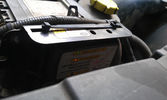
Solenoid engaged11 viewsAfter the engine's running for 5 minutes, the solenoid gets engaged and starts charging the auxiliary battery.14 Jul 2013
|
|

12V to dual USB10 viewsAs the USB cables were running to the booth, I added a 12V to dual USB charger in the booth and connected the USB cables.14 Jul 2013
|
|

New switch18 viewsNearly 5 years ago, I fiddled with some push-buttons, until one day I came across those marine Contura rocker switches :)
The remote control is the switch just behind the EPB.14 Jul 2013
|
|

Modified Wiring diagram for the added electrical bits25 viewsI made this wiring diagram during the cleanup I did lately.
I completely removed some 'old' electrical bits I had installed and used the occasion to document every left and new part.14 Jul 2013
|
|
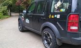
Overall view18 views25 May 2013
|
|
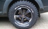
Close up16 views25 May 2013
|
|
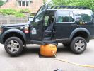
Bushranger test @ home179 viewsThe third trial proved succesful, but I still should have placed it a bit more underneath the car itself19 Jun 2008
|
|

119 views28 May 2008
|
|
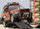
150 viewsthanks to Paul Coens28 May 2008
|
|
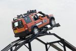
165 viewsthanks to Paul Coens28 May 2008
|
|
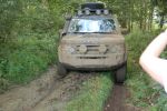
216 views13 Oct 2007
|
|
260 views13 Oct 2007
|
|
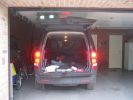
230 viewsLED\'s instead of ordinary bulbs, brake applied05 Jul 2007
|
|
252 views13 May 2007
|
|
495 views06 May 2007
|
|
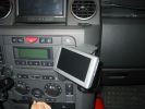
326 views31 Mar 2007
|
|
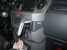
330 views31 Mar 2007
|
|
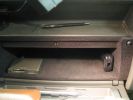
412 viewsAdded a card-reader and ethernet-usb :)
Planning on adding BT and a tiny keyboard ...08 Jan 2007
|
|
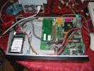
512 viewsInterior of the PC23 Dec 2006
|
|
488 viewsIn BLUE :)21 Dec 2006
|
|

533 viewsAdded an extra switch to the + leading to my PC and to the MP3 changer. As such I can cut off the power to both systems when needed. Learned that one after 2 days constantly working in the car, lighting the whole thing up during 2 days and noticed I couldn't start anymore :D. Saved by my wife's Freelander next to me :)
Also to be seen is the remote controller of the MP3-changer.21 Dec 2006
|
|

416 viewsSwitch in up position, bright controller. I love the blue. A pitty all the other displays in the car are in green.21 Dec 2006
|
|
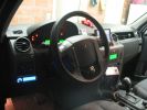
416 viewsUp and ready to go21 Dec 2006
|
|
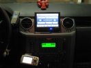
529 views21 Dec 2006
|
|
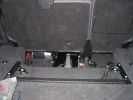
510 viewsMP3-changer and PC beneath the back seats (5 seater). Left and right, 2 USB hubs21 Dec 2006
|
|

506 viewsSetup finished, 7" touch screen, moved around the mobile and the GPS, added an antenna to the GPS for improved reception, since it (obviously) couldn't receive anything at its new position21 Dec 2006
|
|

471 views@ home, we have 2 remote controlled garage doors. So I installed the remote controller in the car, added 2 buttons and off we go. Lucky me the controller worked at 12V anyway :D
I'll add a LED onto that one, so I'm sure it works when I press :)21 Dec 2006
|
|
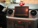
469 viewsAnother view of the screen21 Dec 2006
|
|

357 views.. of the GPS21 Dec 2006
|
|
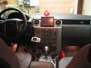
426 views... of the setup21 Dec 2006
|
|
173 views21 Dec 2006
|
|
158 views21 Dec 2006
|
|

460 viewsPrevious installation.
Only my GPS, Mobile and MP3 changer in the back (controller seen on later pictures)21 Dec 2006
|
|
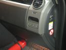
461 viewsFirst step in the journey, installed USB ports.
At the time I installed these, the goal was to use them in combination with the car-computer that resided in the back.
In the meanwhile, I dismantled the car-computer and nearly everything that was connected to it (touchscreen front, Wifi, DVB-T ...).
I kept the USB outlets in the front and turned them into charger for the appliances missus brings with her when we're on holiday. Mainly her iPod and smartphone ...21 Dec 2006
|
|
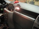
433 viewsA glimpse of the final installation, with a working map-reading light. In case the GPS doesn't work ;p
This is an old picture as the touchscreen is removed already.
However, I kept the reading light.21 Dec 2006
|
|
391 viewsThe light in 'its resting place'21 Dec 2006
|
|
|
|