| Search results - "Side" |
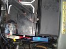
137 viewsThe weatherproof junction box fits neatly down the front of the battery, all contained inside the battery box.
|
|
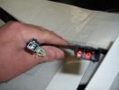
heated seat (base) wiring410 viewsThe Small connector takes the plug from the seat back pad, the larger connector (with red) is fitted into the multiplug casing uder the seat - the male side of this is already pre-wired.
|
|
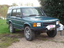
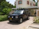
50 viewsD44 front winch bumper. Ali washer bottle. D44 rear h/d bumper. centre diff lock. 235x85x16 pirelli muds. OME +2" springs & shocks. front diff guard. side tree bars. wired for roof CB. Aux fuse block. safari snorkel. extended wading tubes. the list goes on...
|
|
4 views
|
|
4 views
|
|

3 views
|
|
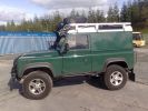
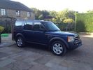
Side73 views
|
|
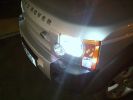
White side light bulbs and 3w 501\'s in the side marker58 views
|
|
At the seaside64 views
|
|
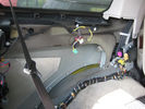
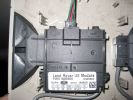
pdc module in rear passenger side43 views
|
|

pdc module in rear passenger side37 views
|
|
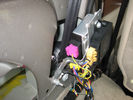
pdc module in rear passenger side38 views
|
|
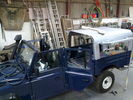
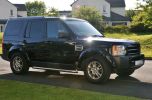
side129 views
|
|
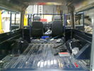
Inside113 views
|
|
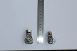
114 viewsside by side shows the larger one adapted at the base
|
|

Estrarre il circuito stampato con la batteria - Exctact the printed board with the battery18 viewsRimossa la parte superiore del contenitore, estrarre il circuito stampato sollevandolo leggermente dalla parte della batteria.
Removed the top of the box, pull out the printed circuit board slightly lifting from the battery side.
|
|
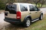
View of right side166 views
|
|
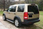
Left side view149 views
|
|

07 Back side of failed tyre340 viewsThis is the back of the blown tyre. It looks like any other worn tyre which has run a bit while flat. Note that we were running on wider 19" RRS wheels (have 4 19" MTRs + 1 old A/T on the original 5 wheels). Also have a rear-mount spare tyre holder which is really convenient with the wider rim and the fact that the tyre was still hot (it had some melted rubber on the other side!!)
|
|
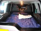
Ensuite or presidential suite ?1208 views
|
|
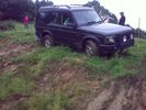
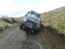
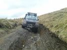
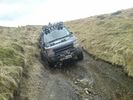
Almost a roll, but not quite...55 viewsI\'d \'launched\' myself at a 6ft hill and got to the top- but at an angle- the offside rear gripped and pulled us around to the right- perilously close to the edge... time for spare undies I think...
|
|
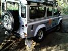
Same holes as the disco, took a picture from the right side. Picture taken at Offroad-Training in Linthe/Germany111 views
|
|

A few mods later26 viewsPro-Speed rock/tree sliders
LED side lights
LED interior lights
|
|

latest spots - side on393 views
|
|

1 ICE Loom - Behind boot trim drivers side. TMC and Nokia modules91 views
|
|
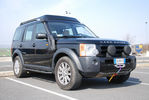
Discovery 358 views
|
|
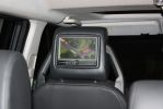
Passenger side DVD109 views
|
|
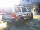
Its - 3 c outside Llanchinda Farm Our B&B For Rally GB 99 views
|
|

238 viewsThe roof panel (inside) with the internal bracket
|
|

148 viewsThe roof panel (inside)
|
|

135 viewsThe bracket (inside)
|
|
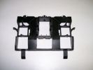
142 viewsThe bracket with sections removed (inside)
|
|
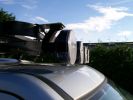
261 viewsOriginal Frontrunner brackets, but installed upside down to reduce the total height
|
|
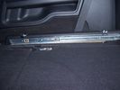
Side runner in position showing front lower than rear.29 views45%
|
|
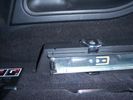
Close up of side runner, showing load hooks countersunk into runner .23 views50%
|
|
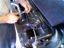
Putting all the bits back in52 viewsNotice the rope (Kevlar) coming out of the actuator box on the right side.
|
|

The old Trooper parked outside the house in 2009.25 views
|
|
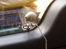
Inside view of camera69 views
|
|
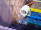
Outside view of camera64 views
|
|

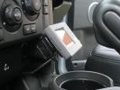
Radio location537 viewsMy remote head UHF CB mounted on the front of the ashtray, ham HF/VHF/UHF remote head radio mounted on a block in the coin tray and my GPS on a turned wooden block in the cup holder. Both radios are under tha driver and passenger seat and the antenna for the GPS is suction mounted inside the windscreen.
|
|

49 views
|
|
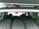
Thirteen Up84 views4 MTR\'s and 4 Sport 255/55 19\'s inside, One 18" Type 2 Mark 1 underneath and 4 18" Type 2 Mark 2\'s on the road
|
|

81 views
|
|
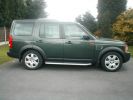
my new car281 views
|
|

13 views
|
|
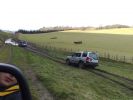
Taking the High road (due to side steps) Doh117 views
|
|
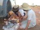
16 All the remains of a D3\'s parking brake371 viewsAfter 4 hours of hammering, finally removed the disk/park brake drum, and nearly all the parking brake bits fell to the ground. Cut rhe remaining brake cable loose as it was wrapped around the hub and a bit melted. Also having 2 jacks + 2 jack stands will support 4 hrs of hammering on the side of my D3.
|
|
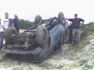
Range Rover upside down on D3 event day 18th September421 views
|
|
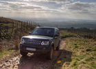
D4 HSE on Hartside Pass106 views
|
|
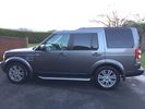
Thread upload9 viewsImage uploaded in new thread
|
|
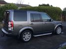
Thread upload7 viewsImage uploaded in new thread
|
|
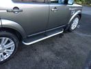
Thread upload9 viewsImage uploaded in new thread
|
|
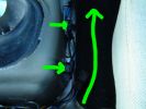
RH Side Ctr Csle45 views
|
|
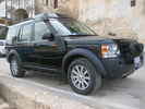
Disco 3 right side37 views
|
|

Inside the kickpanel4286 viewsRed = Left Channel
Blue = Right Channel
Black = Screen
|
|

Bentley 97 views
|
|
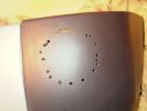
Drilled all round the marked pattern inside then used Dremel to cut out neatly810 views
|
|
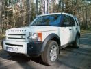
left side68 views
|
|
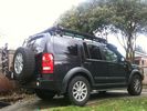
Thread upload5 viewsImage uploaded in thread 188736
|
|
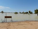
We drove this track in 2008 - East side of 'Big Red' Simpson Desert22 views
|
|
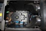
75 viewsInside the cubby box
|
|
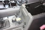
98 viewsAll 4 switches in place.
Driver's side switches are:
. Parking sensors master switch
. Reverse camera off/on/reverse-tiggered
Passenger side switches are:
. CarPC off/on/ignition-triggered
. 12V Regulator off/on/ignition-triggered
|
|
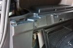
91 views12V socket done. This is permanently powered by the Aux battery. Another one was done on the other side, though that one required drilling the hole with a 29mm hole saw as there wasn't an unused hole on that side.
|
|
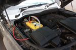
124 viewsOptima Yellow Top in battery box. This is the version with side terminals so there will be some modifications to be done to fit
|
|
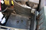
112 viewsDue to the side terminals protruding out the side and affecting the battery clamp, I found the battery will fit better if it could be pushed a few millimeters towards the engine. This lip will have to be removed.
|
|

91 viewsBattery clamp needs to be modified due to the mouldings on the battery top to the side terminals. All that is needed is to cut off the bit as seen.
|
|
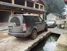
outside hotel27 views
|
|
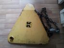
Clamp - outside25 views
|
|
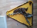
Wheel clamp26 viewsinside
|
|
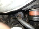
Rear ARB bolts (Near side)45 views
|
|
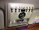
Roof Control Panel31 viewsThe "clean" side
|
|
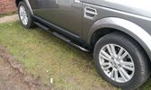
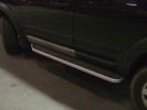
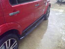
Side Step Bars Tubes with footstep243 views
|
|
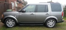
Side Step Bars Tubes Tinted Windows378 views
|
|

Tagom Tires Country Track 17" - Inside25 views
|
|

Spot of greenlaning in the Kent countryside!88 views
|
|
Thread upload0 viewsImage uploaded in thread 172661
|
|

rainbows19 viewswalked past this....side "vents"also tricolour.
|
|
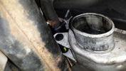
Thread upload122 viewsBottom end Passenger side after original LR hose removed
|
|
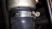
32 viewsNearside hose replaced with silicone type
|
|
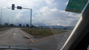
switch16 viewsthe point where you switch from right to left side road.
Laos is drive on right..Thailand left
|
|
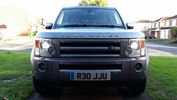
31 viewsLed sidelight and 6000k xenon
|
|
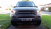
39 viewsLed sidelight and 6000k xenon
|
|
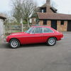
MGB GT V862 viewsNearside
|
|
Side view of connector9 views
|
|
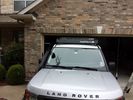
low profile solar panel203 viewsThe low profile solar panel, can be seen here, as the fine white line under the light bar. The way it's laid out, the panel should generate decent power between 10am and 4pm depending on the time of year, from the sides or front, with no shadows. Grape Solar 100W flex panel.
https://www.facebook.com/DifferentialPartsUS
|
|
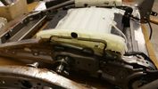
Side Bolsters6 views
|
|

Thread upload9 viewsImage uploaded in thread 135884
|
|

Thread upload9 viewsImage uploaded in thread 135884
|
|
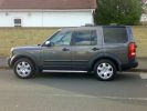
D3 side view307 views
|
|

C0506R56 viewsDescription: ABS module
Location: Rear of engine compartment - driver side
|
|
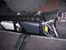
HF radio on RH side Inverter on LH. Frame is fitted behind second row of seats. (I have removed 3rd row as they will never be used)307 views
|
|
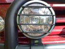
Drivers side spot.152 views
|
|
Thread upload11 viewsImage uploaded in thread 185475
|
|
Riverside in Durham this morning57 views
|
|
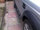
My new slider/steps - sideview offside264 views
|
|
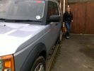
My new slider/steps - nearside145 views
|
|

Thread upload8 viewsImage uploaded in new thread
|
|
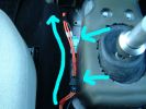
LH Side Ctr Csle50 views
|
|
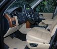
Front seats24 views
|
|
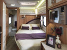
12 viewsinside van 2
|
|

Thread upload7 viewsImage uploaded in new thread
|
|

Drivers Side Headrest108 views
|
|
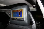
Drivers Side DVD110 views
|
|
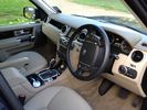
Almond Insides15 views
|
|

Thread upload8 viewsImage uploaded in new thread
|
|
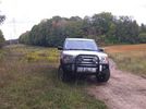
Ooops, found the mountain bike trail. KW Hydrocut15 viewswe were out one day and suddenly I seemed to recognize the power lines, and the fact that the mountain bike trail runs alongside the lines.
This is obviously a wide section of trail, but it's still the KW Hydrocut mountain bike trail.
|
|
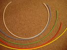
6mm Heat Shrink colours 362 viewsI decided to colour code the tubing so I used 6mm electrical heat shrink.
As there is no apparent colour coding re the 3, I tried to emulate the P38 coding; #1 LR red, #2 RR blue, #3 LF yellow, and #4 RF green. This was not doable as both left side air springs have green coloured tubing coming off the top of the front and rear air springs. I therefore arbitrarily chose the Left Rear to be red; Left Front green; Right Front yellow; Right Rear blue; and for the air compressor supply line, White coloured heat shrink. Since two new lines tie into each air spring line, I made the line between the air spring and the FASKIT, a single solid colour, and the line from the FASKIT to the valve block, White, plus the related appropriate solid colour.
|
|
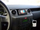
Navi Becker and iPod285 viewsThe Becker Highspeed II was installed in the bin with power connected. Works great, even TMC worked inside the garage right away!
|
|

Thread upload39 viewsImage uploaded in thread 102519
|
|

Sideview of gearbox plate620 views
|
|
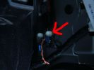
7 ICE Loom - Earth location B piller drivers side69 views
|
|
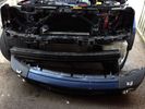
Thread upload39 viewsImage uploaded in thread 102519
|
|
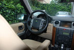
Drivers side21 views
|
|
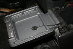
08273 viewsRan the iPod connection up behind and through the center console. I'll be puting an iPod holder in the inside of the console lid.
|
|
911 inside90 views
|
|
10 viewsInside van
|
|
Side87 views
|
|
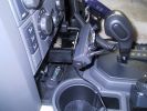
UHF CB438 viewsThe remote head of the GME TX3400 was mounted on the front of the ashtray after unclipping the ashtray facia. The head is very light, double sided tape was used plus 1 screw to hold it.
|
|
Antenna Bracket388 viewsThis was bent from a piece of 3mm x 25mm alloy flat bar. I used automotive grade double sided tape and two screws to fasten it. I have a dual band VHF/UHF antenna on this bracket
|
|
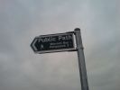
Sign on road-side183 views
|
|
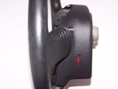
17 viewsThis is the access hole, one on either side.
|
|

Land Rover Aerial Fin images for both Glass and Metal Roof Disco3 / LR3850 viewsAs well as the two different fins, this pdf also shows the plastic blanking plate for glass roof vehicles where no fin is installed.
The glass roof fin is secured by two security screws from the top into a plastic frangible glue on gasket. The hope is that when struck, the fin will shear off and not crack the glass roof. Re the metal roof design, the fin is secured from underneath via two nuts.
The pdf also shows the various electrical bits related to the antennas. In the UK, the fin would house not only a cell phone antenna but the TV and satellite radio antenna electronics as well; in the States, the Sirius sat radio antenna and a G type cell phone antenna if the phone kit was installed would reside within the fin. The SAT NAV GPS antenna is located within the High Mount Brake Light plastic mounted to the upper rear hatch.
|
|

Thread upload1 viewsImage uploaded in thread 203155
|
|
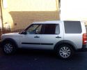
After Side Protection and Tints127 views
|
|
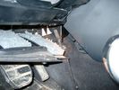
Air Conditioner Drain Hose on Drivers Side (LHD)2258 viewsThe corrugated rubber bit above and to the right of the gas pedal is the drain hose that goes down thru the carpet and floor sheet metal.
While it is bit hard to figure out from the jpg above, there is a rubber "strap" attached to the top of the corrugated hose that one uses to pull on to drag the hose up back around the black plastic heater "pan" drain. The same drain hose arrangement is on the other side as well.
One could I suppose run a plastic snap tie around the vertical pull strap if one was concerned about the hose slipping off again. See also the other jpg sketch which is from the Land Rover manual.
|
|

221 viewsSide view of airbag with home made tool connected.
|
|
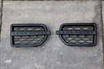
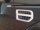
Alloy Side vent LR site143 views
|
|

Alloy side vent116 views
|
|
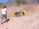
236 viewsOoops!! Tonka lost power and rolled back down onto his side
|
|
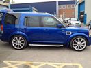
FOR SALE - ONE OFF Land Rover Disco 3 37 viewsOne of a kind Landrover Discovery TDV6 HSE LUX Model 5 door automatic 4x4 diesel evo blue. Upgrades: sidesteps, roof rails, privacy glass, front and rear heated seats/elec seats, landrover tv and headphones, 7 seater black leather, piano black dash/steering wheel, built in fridge, 6 disc changer, sat nav and bluetooth, harman kardon premium entertainment pack, by-xenon adaptive headlights , cruise control and front and rear park distance control, panoramic electric glass roof, 22inch alloy wheels, body kit
|
|
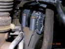
58 viewsOne bolt is visible at the front, but the other two are down the left hand side and best accessed by removing the small plastic guard behind the bumper. I also removed the small metal radiator guard between the bumper and the main sump guard (but that was mostly to retrieve the spanner I dropped!). The only issue with removing the plastic guard is the stupid plastic clips that hold it on may need to be replaced.
|
|
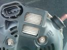
Alternator Plug and B+ terminal910 viewsPictured is the rear of the older Land Rover part # YLE500190 alternator showing the shiny cooling fin of the Regitar VRH2005-142 regulator under.
The first pin in the far left side of the connector is numbered #1 in the LR electrical wiring diagrams and is Battery Voltage Sensing (BVS); the middle pin, #2 receives a Pulse Width Modulated (PWM) signal from the Engine Control Module (ECM), and the right pin, #3 carries a PWM signal back to the ECM. Terminal Pin #2 on the LR wiring diagrams is called Alternator Control or ALT CON; Pin #3 per LR is called Alternator Monitoring or ALT MON.
Pin #1 is similar to what in older designs used to be called A or Batt, but is now called by Denso, S, AS, or Alternator Sensing for this design. Pin #1 also provides power to excite the alternator at startup until the PWM instructions over ride the battery voltage info. Land Rover calls the electronics under the pins a Smart Regulator, ironic, as it has to follow orders from the ECM rather than give the orders - new age thinking I guess. This is different from older design internal regulators that look at just the battery or the electrical buss voltage and then decides itself what to do.
It is almost like we are back to the external regulator designs of old, except that the ECM may decide that instead of telling the alternator to make more power, to load shed, and hence shut down the heated windscreen, seats, or whatever other electrical loads it decides are appropriate. My view is that the "smarts" are in the ECM and that the "regulator" should be regarded if not dumb, then as being a slave to the ECM.
|
|

how to install Altox WBUS-4 in engine room on Discovery 395 viewsthis is to show how to install the Altox WBUS-4 in engine room of a Discovery 3, but i would recommend to install it inside car in footwell, see other PDF in this album
|
|
Thread upload44 viewsImage uploaded in new thread
|
|
Thread upload27 viewsImage uploaded in new thread
|
|

That big!21 views
|
|
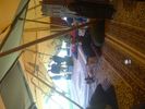
Inside LRE hospitality tent, FOS 210228 views
|
|
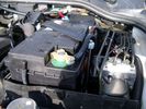
Aux Battery showing ground cable bolt "upside" down 1568 viewsIn order to obtain sufficient height clearance to get the plastic cover back on, I had to install the ground cable to the underside of the battery post connector.
Note the battery vent hose, (approx 5 ft required) is run down into where the windshield washer fluid container is located. There is not much electrical or metal in that area to be corroded by battery gas plus the open end of the vent hose tends to be protected from dirt and stays clean as well.
|
|
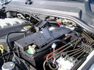
BCI Group 40R Deka 640RMF battery showing vent hose run forward to windshield washer reservoir area 1424 viewsRecessed post "Euro profile" battery to "match" OEM and stock Land Rover bracket; note that the Traxide SC80-LR module is mounted at an angle to allow for the main cable to sit under the cover so cover still closes.
The battery is a nominal 7", (180mm), high, but sits on a 1" battery spacer set under to raise the bottom front end of the battery such that the approx 11", (290 mm), length of the BCI 40R battery rises above the angled plastic nibs at the forward end bottom of the case front; hence sufficient space, (1/4", 5mm) remains at the brake reservoir end.
Also the 40R battery does not have hold down "flanges" on each end; on the sides yes, but not the ends so no additional length is required.
When I had to replace the 40R, this time I installed the shorter, (9.625"), taller, (7.5") Interstate BCI 47 / DIN H5 battery which eliminated the spacer on the bottom and better fit the stock LR tie down bolt lengths. Deka also has a BCI 47 / DIN H5 that would work fine as well.
|
|
173 views
|
|
176 views
|
|
189 views
|
|
190 views
|
|
198 views
|
|
184 views
|
|
185 views
|
|
187 views
|
|
312 views
|
|
336 views
|
|
287 views
|
|
246 views
|
|
231 views
|
|
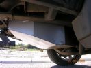
568 views
|
|

Thread upload4 viewsImage uploaded in new thread
|
|

51 views
|
|

Frame Jacking Points showing where holes are located.1078 viewsThe four points marked with the arrows show where the holes in the underside of the frame are located such than one could insert a trolley jack pin type lifting adapter, (or as designed), the official LR scissors jack.
|
|

TransK9?b1041 views
|
|

Thread upload6 viewsImage uploaded in thread 180891
|
|

Thread upload8 viewsImage uploaded in new thread
|
|

Thread upload15 viewsImage uploaded in thread 108637
|
|
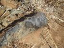
Bad Rock61 viewsbenign looking rock that punctured the sidewall of my new General Grabber AT2 (500km done on tyre)
|
|
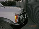
Bar from side430 views
|
|

Sidebar76 views
|
|
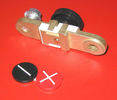
Battery Disconnect side post with + & - caps under view738 viewsThe upper and lower pieces of metal are clamped together but electrically seperate from each other. The connection between the two pieces is via the threaded part attached to the knob. When the knob is turned tight, current will flow between the two sections of metal.
|
|
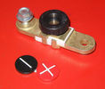
Battery Disconnect side post with + & - caps, top view616 viewsThis disconnect is designed for side post batteries. It can be used on either the + or - terminals. It can also be installed at the "other" end of the battery cable as well. In my install of the Aux battery, I installed this on the negative ground cable where the cable attaches to the body sheet metal. I have never used it but it seemed like a good idea at the time. The main battery hookup is pure stock.
For the hot side of the Aux battery, an Anderson PowerPole was used inline for the cable between the Aux and connecting to the spare bolt hole at the + post of the Main battery cable.
|
|
2 views
|
|
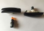
For Sale4 viewsBlack Side Repeaters
|
|
5 views
|
|
Crazy Paving67 viewsThe last place you would expect to find a nice bit of block paving. The 513m summit of Monkside on the DISCO3.CO.UK Kielder day 2009.
|
|
Thread upload8 viewsImage uploaded in thread 199158
|
|
Thread upload9 viewsImage uploaded in thread 199158
|
|
Thread upload5 viewsImage uploaded in thread 180891
|
|

crankshaft bolt22 viewsBolt on left is new one for upgraded oil pump casing. Bolt on right is what came out. Notice damaged end and shortness of bolt. Inside of crank was inspected wirh borescope and threads etc all ok. New bolt goes in and out ok. Few filings inside but otherwise clear. Not sure why old bolt ended up like that.
|
|
side view47 views
|
|
Thread upload29 viewsImage uploaded in new thread
|
|
Thread upload2 viewsImage uploaded in new thread
|
|
inside14 views
|
|

Black Deposits to interior of Brake Light Switch2831 viewsThere are two contacts, one on each side of the vertical plunger under the copper metal. The set of normally open contacts on the left side that carries the power for the brake light filaments, (15 amp fuse F15P), is apparently not heavy enough as the contacts deteriorate and generate the black residue.
The set of normally closed contacts on the other side appear to be sized OK. There is not as much current, (5 amp fuse F66P), flowing thru the contacts to the ABS module, however the contacts are likely adversely affected by the black residue produced by the other deteriorating set of contacts.
One presumes/hopes that the newer replacement switch now has contacts heavy enough to carry the brake light power. It would be ideal if the ABS set of contacts were sealed from the brake light contacts to prevent contamination of the normally closed set of contacts.
|
|

Brake Light Switch, Find, Remove, and Install Instructions 7782 viewsThis is a two page doc outlining where to find the brake light switch, how to remove it, and then install the new one.
Note, do not move the brake pedal when removing or installing the switch. Let the brake pedal hang where it wants to. The switch design is actually cunning, and as such is supposed to make the removal and install fool proof. Hence if you think too much about it, you can wreck the new switch.
If you want to inspect the interior of the switch, wait until you have removed the old switch. You can then just unsnap the blue from the white to get it apart. Inside, the switch is quite simple, (no circuit boards), but it will probably show black dust from failing contacts.
I think the reason the switch fails is that the Normally Open, (NO), contacts of the brake light contacts were made too light to carry the current load for make and break of the tail light filaments. I also think the black dust created then fouls the Normally Closed, (NC), second set of contacts for the ABS circuit. As such, the Normally Closed contacts become intermittent in operation and display as a fluctuating open and closed circuit condition to the ABS system when the ABS should be seeing a steady closed circuit. Hopefully the replacement switch contacts are more robust and may be as I recently replaced my switch again just as a matter of maintenance. While in a redesign, ideally the NC contacts should be sealed or at least separated from the NO contacts, when I inspected the removed switch, this time there was no black dust present.
Probably the removed switch will have a Land Rover oval logo moulded into it, the new one, FOMOCO.
|
|
Brake Switch Visible thru Opening4934 viewsThe blue and white bit is the switch; the sort of gold appearing box,(it is really black), you will not see in your 3 as it is a Smooth Talker brand amplifier for my Blackberry phone antenna. This install is detailed in the SmoothTalker phone antenna section of my gallery.
One way to remove and install the switch is to lower the "horizontal" panel above the brake pedal as shown where the flashlight head is located. To actually remove the switch, you slide your hand thru the gap and rotate the switch clockwise 1/4 turn while watching thru the rectangular opening. Installation of the new switch is the reverse of above - 1/4 turn counterclockwise.
Before you remove the switch, note its orientation - horizontal with electrical wires to the left. That is the way it should look after replacement as well.
The second time I replaced the switch, I did it all thru the rectangular opening and did not remove the horizontal panel - that is experience helping out.
The knee kick you have to remove regardless. It is sort of hinged at the bottom so you just pull at the top and sort of rotate the knee panel and then pull upwards for two plastic "fingers" to clear the slots they reside in.
|
|
Smooth Talker Amplifier Box mounted below near steering column.179 viewsThe gold look box due to the lighting, (actually black), is the antenna amplifier located near the steering column. It can be put anyway but this seemed an OK location as I ran the antenna connector cable rearward from here to the back corner of the 3 and then up to the underside of the roof glass at the rear. The blue/white thing is the brake light switch that often must be replaced. See the Brake Light Switch file within this Gallery regarding the switch replacement.
|
|

Black Deposits on Brake Light Switch Plunger2731 viewsThis jpg I got off another forum and is typical of what one will see when one opens up the removed brake light switch. The black powder is residue from arcing of one of the pair of contacts within.
Hopefully the newer switches with the FOMOCO logo moulded into the plastic are improved from the Land Rover logo marked early units, however I doubt it.
The Ford part number is SW-6572 and/or 7E5Z-13480-A as used on the 2006 to 2009 Ford Fusion's and Mercury Milan's; the Land Rover part number is XKB500110. Cost of switch could be about twenty five dollars. A previous LR part number for the switch was XKB500030, so hopefully the newer LR part number, XKB500110, reflects some improvement in reliability.
It is possible that the new switches are better as I installed a replacement 72,000 km, (45,000 miles) later, at 195,000 km (121,000 miles). When I took the removed switch apart to inspect, it was clean inside. There was no black dust - the switch looked like new, hence they must be improved now.
|
|
Vertical Breather Hose before cutting off OEM cap.1742 viewsThis shows the plastic vertical breather tubing and OEM cap prior to being cut off. The tubing is located on the driver side at the front near the radiator. One cuts about 3/4" to 1" off from the top. The TSB says 20mm.
I tried blowing thru the cut off piece and was not very successful. The cap seemed plugged. I am beginning to think that there was a very good reason for Land Rovers's Technical Service Bulletin, (TSB).
|
|
Thread upload0 viewsImage uploaded in new thread
|
|
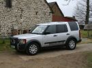
Normandy March 09 - Big Side Stickers Fitted!75 views
|
|
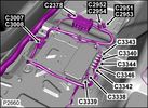
Camera Control Module D451 viewsHarness connection detail, camera module, located beneath L/H passenger side front seat UK D4 spec 2012.
|
|
sidestep86 viewsmounting the sidestep
|
|
86 views
|
|
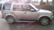
D4 side on70 views
|
|
D3 Side Step Repairs152 viewsHow I repaired my damaged side step after a days offroading at Tong in November 2008
|
|
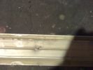
D3 Side Step Repairs155 viewsAluminium trim has been straightend out but need to remove all the old rivets from the rear of the trim.
|
|
D3 Side Step Repairs185 viewsThere are about 10 rivets to drill out. I also increased the hole size to 5.5mm as I will be using larger rivets to hold the trim back in place. 5.5mm is the larger rivet size commonly available at motor factors etc.
|
|
D3 Side Step Repairs161 viewsI then drilled out the holes in the step edge to 5.5mm to accomodat my larger rivets.
|
|
D3 Side Step Repairs164 viewsFinished job all I need to do now is wash it all off. I had already replaced the front door trim using new trim fixers and as you can see it was still dirty.
|
|
D3 Side Step Repairs146 viewsCarefully drill out the old rivet ends. Some were a bit stubborn and I used a small chisel and drift to punch them, out.
|
|
D3 Side Step Repairs162 viewsAgain there are 10 holes to incresae the size of.
|
|
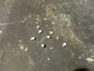
D3 Side Step Repairs145 viewsThe old rivet ends which I removed from the trim. I took one rubber end off the trim and let them all out by shaking it to save them rattling around inside the trim for years to come.
|
|
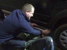
D3 Side Step Repairs166 viewsWhilst I held the trim in place a second person inserted the rivets from behind the step edge. We started in the middle and worked out either way to ensure a snug fit of the aluminium trim.
|
|
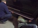
D3 Side Step Repairs168 viewsNearly finished - just the last two rivets to put in. We used a very basic and cheap hand rivet gun which can be bought in places like Halfords for about £10.00 and usually come with a supply of rivets to do the job.
|
|
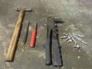
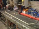
D3 Side Step Repairs150 viewsTools needed for the repair.
|
|
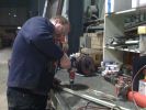
D3 Side Step Repairs149 viewsI then punched out the remaining rivets from the step edge. I used a small hammer and a small punch.
|
|
Kielder D3 Safari122 viewsMonkside 513m - Kielder, Northumberland. G4 Discovery 3
|
|

469 viewsSide steps, light guards, rubbing strips, roof bars, privacy front and rear
|
|

Thread upload0 viewsImage uploaded in thread 183462
|
|
Thread upload1 viewsImage uploaded in thread 183462
|
|
Thread upload6 viewsImage uploaded in thread 1546
|
|
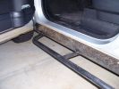
Sill protectors 2735 viewsThe side protection bar comes out a good 170mm. Prevents side panel damage and car-park knocks! Still deciding whether to fit the chequerplate tops, as originally designed.
|
|
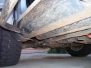
Sill protectors796 viewsThese replace the plastic sill protectors. 4mm mild steel plate, bolted through the existing holes in the side and underside.
|
|

Thread upload9 viewsImage uploaded in thread 146850
|
|
Thread upload0 viewsImage uploaded in thread 203496
|
|
Thread upload3 viewsImage uploaded in thread 205984
|
|
Thread upload1 viewsImage uploaded in thread 203496
|
|
not a rice field in sight29 views
|
|
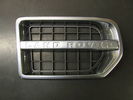
Chrome side vent118 views
|
|
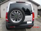
40 viewsThe correct side
|
|
Brackets fitted to underside of A bar using mounting bracket holes.251 views
|
|
This show that the angel of the radio body is diffrent from the original, hence shall some plasic be removed - I used a dremmel and removed 7 mm of the horizontal bar inside 160 views
|
|
Hidden Mic Connector141 viewsMic connector on upper side of head lining just above & behind sun visor
|
|
LRs stick together129 viewsA date plantation alongside a wadi in the Western Hajar mountains of Oman. My mate\'s Disco 2 in company. Cracking drive on this day some 100km off-raod through wadis and mountain graded roads. Sheer, unadulterated pleasure.
|
|
RHS view371 viewsSHows the Front Runner (SA) slimline windcheetah rack which is immensely strong. Takes my 110kg (oh gawd, I must get back on the diet and exercise regime) tramping over it when loading/unloading gear without a problem. Fittings are simply fixed or removed, and IMO very well designed and made. IPF 800 series driving and spots fitted to the front of the rack. IPF cam/reversing fitted each side and to rear of rack for negotiating rocky wadis at night. The G4 stickers were bought off E-bay as a set.
|
|
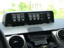
Mud UK switch binnacle453 viewsToo many switches for the roof mounted console, so this binnacle from Mud UK (desigend for the Defender) is an almost perfect match for the leather finished dash in the LR3. Switches, connectors etc bought from them too. From L - R switch functions are:
LH side mounted rack lamps
Driving lamps rack mounted
Spot lamps rack mounted
Bumper mounted driving lamps
RH side mounted rack lamps
Warn winch isolator
Rear mounted rack lamps (reversing)
Telescopic work lamp (fitted behind RH spare wheel)
|
|
Auxiliary power sockets - TracTronics, Australia381 viewsA complete kit including two outlets, wiring etc connected to auxiliary Optima Blue top battery using their very effective SC40 split charge relay. One outlet between rear and front seats, and 2nd alongside loadspace 12v outlet, enables fridge to run when engine is not running, without affecting start capacity or vehicle functions.
|
|
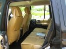
Escape seat covers rear254 viewsJust shwing the good fit of these canvas seat covers made in South Africa. The whole set for a 7 seat HSE £542 with air freight as unaccompanied baggage (inside 5 Front Runner Wolf pack boxes) costing and additional £150 - still a bargain out here!
|
|
TracTronics loadspace power socket 379 viewsThe 2nd power socket fitted alongside the original in the loadspace runs off the auxiliary Optima Bluetop battery to run a fridge when engine is not running. No more starting worries!
|
|
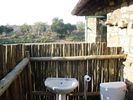
Outside bathroom53 viewsOver looking the Limpopo River with South Africa in the back ground
|
|

View from outside bathroom47 views
|
|
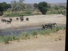
View from inside the house - South Africa in the back ground 32 views
|
|
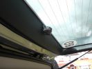
High level camera mounting on inside of tailgate trim52 views
|
|

Mounted in 12v socket from driver\'s side42 views
|
|
Dash Mounting from passenger side43 views
|
|
My Disco3 outside its other home, the City Inn Westminster304 views
|
|

My Disco3 outside its other home, the City Inn Westminster205 views
|
|
Side rails257 viewsThe side rails have been bent up and are touching the sill. At least they have protected the sill.
|
|
Colour coded body side moldings487 views
|
|

74 viewsComing down from the summit seconds before blowing out the front passenger-side tire.
|
|

Thread upload14 viewsImage uploaded in thread 57865
|
|

Thread upload4 viewsImage uploaded in new thread
|
|

Thread upload4 viewsImage uploaded in thread 151040
|
|
Thread upload0 viewsImage uploaded in thread 154757
|
|

Thread upload0 viewsImage uploaded in thread 154757
|
|
Thread upload0 viewsImage uploaded in thread 154757
|
|
Thread upload0 viewsImage uploaded in thread 154757
|
|
Thread upload0 viewsImage uploaded in thread 154757
|
|

Thread upload0 viewsImage uploaded in thread 154757
|
|
Thread upload0 viewsImage uploaded in thread 154757
|
|

Thread upload15 viewsImage uploaded in thread 122630
|
|
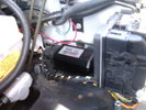
CounterAct Power Supply mounted 244 viewsPicture is blurred, however power supply is 3M two sided tape to the flat black plastic of the second battery compartment just under the antilock brake pipes to the fender side of the brake fluid reservoir. The white wire to the left rear coupler pad runs thru the firewall hole near the steering column. The blue wire to the right front coupler runs across and above the engine following the other wiring looms that cross the vehicle.
|
|

Front Footwell Panel98 views
|
|

83 views
|
|

63 views
|
|
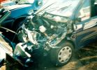
Not much left of bonnet!278 viewsCrash in a Renault Scenic
Head on colition with a Nissan Terrano he lost control came over the central reservation & ended coming at us sideways!
We hit him in the back wheel arch & spun him around so he then hit my drivers side, I walked away having a air bag wife had broken solder coursed by the seat belt, but it did save her life!
Our car was trashed but it did its gob (was only 2 weeks old!) the bonnet tacking lots of energy out of the collision & the inertia staying relatively in tacked.
|
|
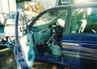
Near side showing interior225 views
|
|

Side damage212 views
|
|
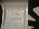
940 kg load marking on inside of spoke416 viewsThis is a typical 940 kg load marking on a Cromodora wheel rated for the 3. In this case, the wheel is the 6 spoke 19" wheel common to the HSE, LR Part # ALY72191U.
|
|
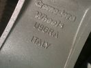
Cromodora brand marking on inside of spoke.323 viewsThis is the Cromodora brand marking on the inside of the 6 spoke 19" wheels, Land Rover part number ALY72191U. Similar brand markings are cast onto the inside surface of the spokes on all Land Rover Cromodora wheels.
|
|
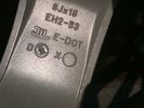
E-DOT and Japan wheel acceptance marking on ten spoke wheels.333 viewsThese are the E-DOT and Japanese wheel acceptance markings on the inside of one of the ten spokes of the 8J x 18" wheel, Land Rover part number ALY72190U or RRC500250xxx where xxx is the colour number, in this case, MNH for Sparkle Silver. There are similar markings on all Cromodora wheels for the 3.
|
|
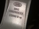
Part number moulded into spoke of 18" ten spoke. 320 viewsThis part number, RRC500250XXX is moulded into the backside of one of the spokes of the ten spoke 18" wheel. An alternate part number is ALY72190U or ALY72190U85 which relates to year and finish.
Another number is RRC500250MNH where MNH is also the finish, probably Sparkle Silver.
|
|

camera54 views
|
|
183 views
|
|

056231 viewsP0562 SYSTEM VOLTAGE (ENGINE SIDE) TOO LOW
|
|
d3 alarm (inside sensors)168 views
|
|
D3 Colour Coded Wheel Arches273 viewsNew Colour Coded Wheel Arches and side tubes.
|
|
side shot220 views
|
|

Thread upload7 viewsImage uploaded in new thread
|
|

Thread upload2 viewsImage uploaded in thread 205597
|
|
55 views
|
|
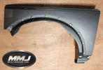
Thread upload6 viewsImage uploaded in new thread
|
|
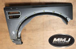
Thread upload5 viewsImage uploaded in new thread
|
|

D3 XS in Burrs Country Park52 views
|
|

D3 XS Wedding58 views
|
|
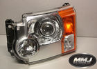
Thread upload3 viewsImage uploaded in new thread
|
|
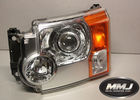
Thread upload6 viewsImage uploaded in new thread
|
|
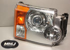
Thread upload3 viewsImage uploaded in new thread
|
|
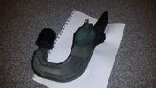
towbar4 views
|
|

Front and Side Clips - Seat Base38 views
|
|

Per replacement of seat base foam - note creasing on right side due to collapsed foam40 views
|
|

Rear side clip removal - seat base44 views
|
|

Seat Base cover front and side clips released43 views
|
|

Seat Base Heating Element Side View37 views
|
|
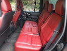
Thread upload5 viewsImage uploaded in thread 176545
|
|
Thread upload5 viewsImage uploaded in thread 176545
|
|

D3 XS in Burrs Country Park58 views
|
|
56 views
|
|

Thread upload7 viewsImage uploaded in new thread
|
|
Thread upload4 viewsImage uploaded in new thread
|
|
Thread upload4 viewsImage uploaded in new thread
|
|
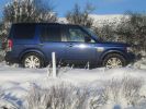
166 views
|
|
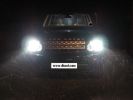
D4 hid kit installed and outside in the dark 6000k conversion.284 views
|
|
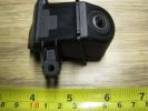
D4 Rear camera side view126 viewsUsed on surround camera system.
|
|
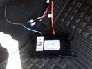
D4 Bluetooth AH42 10F845 AA module connected to 12VDC and MOST1191 viewsThis jpg shows the MOST bus connected to the AH42 10F845 AA module used in the D4 as well as +12VDC power from F58P connected. The power is split with a Y harness as the IHU (radio) for some reason required +12VDC power to the C2115-10 "mute" pin to keep the radio/CD audio from muting all the time.
With power on the pin, the radio audio does mute as it should when the cell phone rings and the hands free connects. The brown conductor feeds to C2115-10 and the blue to the module.
The module tucks up and hides behind the grey plastic section covering the forward portion of the passenger side tranny hump for left hand drive vehicles; for RHD, it would be located on the left side.
The pairing code is 2121 with this setup and not 1234 or 0000.
|
|
230 views
|
|

Thread upload69 viewsImage uploaded in thread 103390
|
|
213 views
|
|
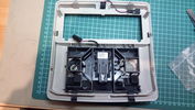
Rear side of finished roof console54 views
|
|
93 views
|
|
83 views
|
|
105 views
|
|

Disco3 on the move in Dangalli Conservation Park - at speed (south of Yunta)177 viewsMusic heard in video is from the stero blasting away inside the Disco - and yes...that was a cattle grid being crossed at the start :-)
|
|

Thread upload7 viewsImage uploaded in new thread
|
|

Thread upload8 viewsImage uploaded in new thread
|
|
Thread upload8 viewsImage uploaded in thread 126243
|
|
Thread upload11 viewsImage uploaded in thread 126243
|
|
Mitac Mio 168 PDA400 viewsPDA with built in satellite reciever mounted into cradle mounted on "l" bracket to avoid drilling the side of recess.
|
|
Bespoke Colour Coded side vent with Racing mesh93 views
|
|

Deka Battery Dimension Data613 viewsThe battery size that I installed for my auxiliary was a BCI 40R battery as it was for me the easiest to fit and was also a cranking battery. The case profile was such that no tie down fins were located on either bottom end, (sides yes), and length wise, it was only about 11" (290 mm) long. As such, I did not have to grind the nibs at the front bottom of the plastic surround.
I did however raise the bottom of the battery above the angled nibs as I set the battery on a 1" (25mm) high plastic spacer. The total height, (battery plus spacer), was about 8" (200mm) so the battery top still fit under the Land Rover factory cover.
For the Aux battery, when I replaced the 40R, I installed an Interstate BCI 47 which is similar in size to a DIN H5. I was therefore able to eliminate the vertical spacer as the Group 47/H5 is the same height as the DIN H7/H8 stock LR spec starting battery. As such, the standard battery tie down bolts can be used without modification. The Group 47 battery is 9 11/16" long x 6 7/8" wide x 7 1/2" (190mm) high.
|
|
Ours...169 views
|
|
Our disco151 views
|
|
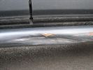
Dented side rails264 viewsShows how thin the metal is.
|
|
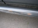
286 views
|
|

D3 reqar diff lock181 viewsView from right rear tyre well, left rear tire/rim visible on other side. Actuator motor visible
|
|
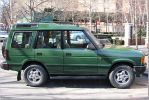
Side On2148 views
|
|
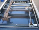
Awning205 viewsThere are many bolt slots in the expo rack, bottom ribs,
side rails on the inside and on top of rear rail.
|
|
Awning182 viewsSide view of mounting bracket, made of 6mm x 50mm ali flat bar.
|
|

Nearside close up shot with boot trim removed250 views
|
|
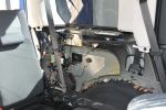
Nearside shot with boot trim removed288 views
|
|
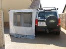
Awning243 viewsI have dual mounted awnings which can convert to tents if required. The outer side walls are an off the shelf purchase, but
the inner ( vehicle side )have to be made to spec.
|
|
266 viewsHome made long range tank, 4.5 mm ali, welded inside & outside on bottom sections.
|
|
74 views
|
|
74 views
|
|
71 views
|
|

256 viewspulled off the factory plastic and found 2 6inch cracks in the drivers side top in front of head light
|
|
Rear Side (2)343 views
|
|
Rear Side View364 views
|
|
Side View332 views
|
|
Thread upload27 viewsImage uploaded in thread 101157
|
|

Headlight mod and D4 grill mod62 viewsFirst tackle of mods to my D3, First attempt was the D4 grill, then the de-orange of the headlands, Also installed LED sidelights and indicators
|
|
Tan Hill Pub Meat 1.03.0955 viewsCountryside in Cumbria
|
|
Roamingman decides that he wants some of the Scottish countryside 109 views
|
|
80 views
|
|
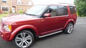
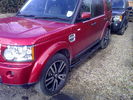
49 viewsSide Bars on Red D3
|
|
110 views
|
|
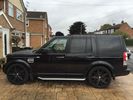
Thread upload9 viewsImage uploaded in new thread
|
|

New D4 Rear Lights105 views
|
|
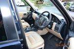
21 views
|
|

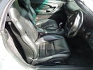
Passenger side seat....106 viewsBlack leather stiched in silver...
|
|
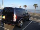
Seaside12 views
|
|
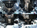
Thread upload1 viewsImage uploaded in new thread
|
|
Thread upload1 viewsImage uploaded in new thread
|
|

Side loading still in place...for now60 views
|
|
dented side !18 views
|
|

Disco 3 - Suspension Leveling & drop check worksheet32 viewsUsed to work out how much your disco drops on its suspension and if its outside of the standard tolerances.
If you have any suggestions on how it can be improved please let me know.
|
|

Side mount antenna23 views
|
|

Thread upload39 viewsImage uploaded in thread 111640
|
|
Thread upload70 viewsImage uploaded in thread 175673
|
|
Thread upload3 viewsImage uploaded in new thread
|
|
Thread upload77 viewsImage uploaded in thread 175673
|
|
Thread upload97 viewsImage uploaded in thread 175673
|
|
Thread upload87 viewsImage uploaded in thread 171927
|
|
Thread upload68 viewsImage uploaded in thread 171927
|
|
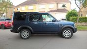
Thread upload78 viewsImage uploaded in thread 171927
|
|

Donald outside of our holiday cottage, on the Isle of Wight168 viewsWe made the most of the early summer (March) and had a great time on the IoW!
|
|
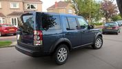
Thread upload70 viewsImage uploaded in thread 171927
|
|
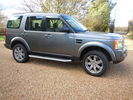
Thread upload19 viewsImage uploaded in thread 107551
|
|
Thread upload16 viewsImage uploaded in thread 107551
|
|
168 viewsVanstyle sunblinds side view.
|
|
New Speaker Cables.107 viewsThis is the door connector, Main loom to Right, Door side to the left. to the top of the connectors you can see green and Green white wires which are the speaker ones. The door wiring is premium and has two pairs, the main loom was a 1 pair high line, so i am adding the pair you see (one already pinned up) to upgrade the loom to premium.
|
|

Thread upload18 viewsImage uploaded in thread 170806
|
|
Actuator box underside 62 viewsUsed a clove hitch with plastic zip tie with 1/8" Kevlar rope
|
|
Driver (RHD) Sunroof Drain Pipe96 views
|
|
Thread upload0 viewsImage uploaded in new thread
|
|
Thread upload0 viewsImage uploaded in new thread
|
|
Front passenger side door speakers77 views
|
|

Thread upload8 viewsImage uploaded in thread 22757
|
|
8 views
|
|

Driver's Side Temperature Blend Door Actuator11 views
|
|

Thread upload6 viewsImage uploaded in new thread
|
|
Thread upload20 viewsImage uploaded in thread 116751
|
|
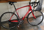
Drive Side44 views
|
|
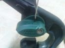
knock the locking pin downside with a small screwdriver167 views
|
|
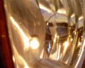
Old Yellow Sidelight91 views
|
|
New Blue Sidelight104 views
|
|
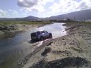
disco 3 on a scary side angle85 viewsdoes\'nt look to bad here, totally different story when your inside it. spare jocks anybody??
|
|
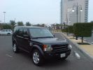
Painted wheel arches and side grill304 views
|
|
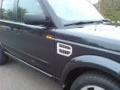
Bright finish side grill264 views
|
|
MY14 Humidity sensor cabin side11 views
|
|
MY14 Humidity sensor windshield side11 views
|
|
Passenger side Airbag35 viewsAirbag seams cracking
|
|
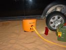
Spread the laod133 viewsEncouraged that the load on the jack still doesn\'t cause any sink in, even in soft sand, with most of the weight of the car on it due to the side slope.
|
|
Spyder LEDs side view146 views
|
|
Off the ground143 viewsCar is on a desert sand sideslipe towards the camera - worst combination I could think of. Fully inflated, jack lifts the rear off by about 25mm, with suspension in extended mode.
|
|
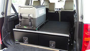
Ironman Drawers and Fridge Slide111 viewsI hate kitsets, over 100 bolts to assemble this unit and lost gallons of sweat, must have read the instructions a hundred times or more but final product does not look so bad. A few bolts hanging out the sides of both slide and drawers that may catch things so time will tell if I made the correct purchase.
Maybe one day I will make some side wings to cover the sides properly.
|
|
Clear side repeater and bright finish grill198 views
|
|
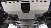
GOE Bash Plates117 viewsGreen Oval Experience Bash Plates. Front, Transmission and Compressor.
Might have to mod the front one a bit to let air into the trans cooler, it sits over the outside of the ARB bar which has vents for the cooler. If I cut slots in the Allow Plate to match those might do the trick.
I added a rear bolt to the Compressor Plate as it looked like it could get hooked on something and tear off. Two bolts onto the slider and two up onto the chassis now.
|
|
161 views
|
|

Lead Car Entering the Finish115 views7 May 2007 - My D3 on duty as lead car in shinfield 10K road race. what a nightmare driving at low speed in the rain. Clock was mounted on standard crossbars. connection to additional batteries in boot cable thru side window. There is a small offroad section (actually an un-made road) Oaklands Road, Shinfield, Reading (suggest anyone test driving in the Reading area take this road)
|
|
Side Steps...bit missing!!122 views
|
|
connectors - back side of the center arm rest121 views
|
|
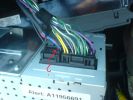
CD 400 back-side connectors145 views
|
|
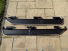
VPLAP0035 Side Steps112 views
|
|
67 viewsrainsensor as seen from outside. Note tinted film around sensor
|
|
Sump guard, side protection over bumper436 views
|
|

Inside Bendethera Cave73 views
|
|
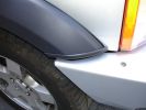
ARB Bull bar - closeup of drivers side showing trim finish.242 views
|
|
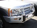
ARB Bull Bar Installation, Front side view. Colour coded to Vehicle.295 views
|
|
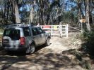
Locked gate and wire rope fence at start of Limeburners.62 views$11,000 fine if you are caught in a vehicle on the other side!
|
|
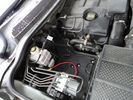
71 viewsAux battery tray - I found out you can remove the side as well as the top cover of the compartment.
|
|

59 viewsYou can see how the spot to mount the control box has the long flat section to the left - so I mounted the box upside down to allow the 2-sided tape to stick to this bit.
|
|
side view437 views
|
|
Yet another use for side steps...270 views
|
|
sidelight access aperture252 views
|
|
| 1348 files on 4 page(s) |
 |
1 |  |
 |
 |
|