| Search results - "harness" |

Chassis harness to main harness107 viewsDescription: Chassis harness to main harness
Location: Below LH rear wheelarch
Part No.: YPC909640 Colour: LIGHT GREY Cavities: 18WY
Harness: CHASSIS HARNESS
|
|
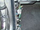
N/S Kickpanel wiring harness for AUX input4275 views
|
|

B post door plug14 viewsRear door wiring harness plug to B post
|
|
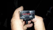
Connector on underseat harness for heated rear seats16 views
|
|
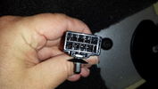
Connector from Main Loom to Heated Rear Seat Harness17 views
|
|

Air suspension Control Module98 viewsDescription: Air suspension Control Module
Location: RH 'A' post
Part No.: YPC500830 Colour: NATURAL Cavities: 20WY
Harness: CABIN HARNESS
|
|
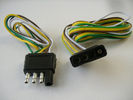
4 pin NAS flat connector from NAS small trailer377 viewsThe connector with the three exposed pins is the end that would commonly be located at the trailer hitch end, (front), of a small NAS lightweight trailer that has no electric brakes. This plug would connect into the flat 4 pin connector at the rear of the 3.
Note the order of the pin functions and wire colours: White is ground; the next pin is for tail/marker lights using the Brown wire; the Yellow conductor is for the left turn signal, and the far pin uses the Green conductor for the right turn signal.
There is no separate brake light conductor as NAS spec vehicles most often combine the brake and signal light functions to the same bulb filament rather separate filaments in different bulbs. The LR factory harness resolves that design difference.
Fortunately, the Land Rover NAS assembly pin order for the 4 pin flat plug maintains the above described conventions.
|
|
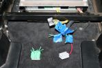
04272 viewsThe green wiring harness is the speaker outputs. Green is + and Green with white stripe is -. We tested all the wires with a 9V battery to figure out which went to what speakers then clearly labeled them as we did.
|
|

Sensor-Height-Rear-LH65 viewsDescription: Sensor-Height-Rear-LH
Location: Below LH rear wheelarch
Part No.: YPC909530 Colour: BLACK Cavities: 3WY
Harness: CHASSIS HARNESS
|
|
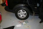
06256 viewsWires from the wiring harness of the V1000 to hook up.
|
|

C2243R72 viewsDescription: Main harness to engine compartment harness Location: Behind passenger compartment fusebox
|
|
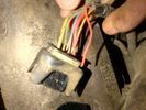
Broken wire Transfer box actuator motor harness 2 - temp sensor wire23 viewsBroken wire Transfer box actuator motor harness 2 - temp sensor wire
|
|
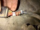
Repaired Transfer box actuator motor harness 2 - temp sensor wire22 viewsRepaired Transfer box actuator motor harness 2 - temp sensor wire
|
|
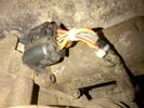
Repaired Transfer box actuator motor harness 3 - temp sensor wire23 viewsRepaired Transfer box actuator motor harness 3 - temp sensor wire
|
|

Alternator female plug looking down into top367 viewsThis shows the plug connected to the alternator wiring harness looking down into the top of the plug.
The cavity marked 1 is the AS or BATT SENSE and the wire colour most likely has Brown/Green on it.
The cavity marked 2 is the RC or ALT CON and the wire colour most likely has Red/White on it.
The cavity marked 3 is the L1 or ALT MON and the wire colour likely has Green/White on it.
I say "most likely" as the wire colours are not always the same on all vehicles.
Also the terminal 1 conductor destination is more likely C0570-175 rather than per the jpg.
The #3 pin is located closest to the big B+ terminal.
|
|
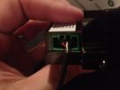
Aux Input Wiring Harness69 viewsUsed a modified PC CD interface cable to connect to stock female harness. Pins 3(R), 4(L), 5(G)
|
|

Thread upload1 viewsImage uploaded in new thread
|
|
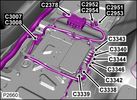
Camera Control Module D451 viewsHarness connection detail, camera module, located beneath L/H passenger side front seat UK D4 spec 2012.
|
|
Rear passenger (left) wire harness channel41 views
|
|
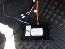
D4 Bluetooth AH42 10F845 AA module connected to 12VDC and MOST1190 viewsThis jpg shows the MOST bus connected to the AH42 10F845 AA module used in the D4 as well as +12VDC power from F58P connected. The power is split with a Y harness as the IHU (radio) for some reason required +12VDC power to the C2115-10 "mute" pin to keep the radio/CD audio from muting all the time.
With power on the pin, the radio audio does mute as it should when the cell phone rings and the hands free connects. The brown conductor feeds to C2115-10 and the blue to the module.
The module tucks up and hides behind the grey plastic section covering the forward portion of the passenger side tranny hump for left hand drive vehicles; for RHD, it would be located on the left side.
The pairing code is 2121 with this setup and not 1234 or 0000.
|
|
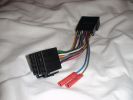
Wiring harness for Kenwood to Disco 359 views
|
|
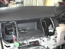
wires pocking through hooked up to base harness644 views
|
|
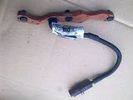
Glowplug Harness41 views
|
|

Thread upload2 viewsImage uploaded in thread 196635
|
|
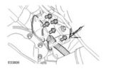
24 views
|
|

Thread upload16 viewsImage uploaded in thread 50790
|
|

Thread upload16 viewsImage uploaded in thread 50790
|
|
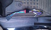
56 viewsThe OEM 2 ISO harness. Notice the red and yellow, which are important for my radio. Not having the red connected simply didn't activate the radio (so I wonder what the radio does with the permanent 12V)
|
|
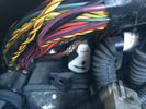
Harness chafing18 viewsWire insulation worn through with short to battery
|
|

Harness chafing20 viewsHarness chafing area
|
|
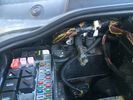
Harness location15 viewsArea of harness that chafes against battery terminal
|
|
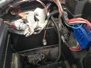
unknown harness70 views
|
|
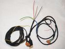
cable harness63 views
|
|
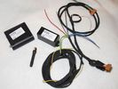
LR3 Bundle & cable harness70 views
|
|
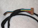
GSM box end of the cable harness75 viewsGreen, blue & orange wires not connected
|
|
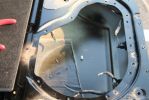
Subwoofer Install271 viewsThe stock sub has 2 sets of wires running to it. Both of these wires lead back to the stock amp.
The new sub only needs two wires - a positive and a ground. So, we just cut the stock wiring harness off the wires in the tail gate and wired them together. On the other end of these wires, we did the same thing.
|
|

LA204-003 - Technical Bulletin - Air Suspension Height Sensor Connector Overlay Harness120 views
|
|

LA501-020 - Technical Bulletin - Supplemental Restraint System Overlay Harnesses59 views
|
|
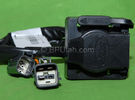
Harness section that runs behind the rear bumper.405 viewsThis is the harness section that clips up inside the rear bumper and includes the circular 7 pin, (6 flat +1 round), NAS socket, and also the 4 pin NAS flat connector.
The two small plug ends connect under the rear left tail light to the harness section that exits from the interior.
The Land Rover part number for the NAS trailer tow kit, (both cables), is YWJ500220.
|
|

Harness that connects inside left rear compartment.435 viewsThis is the harness section that connects behind the left rear interior access panel and exits thru the large grommeted hole to below/behind the left rear tail light.
Note the two rubber grommets on the harness as there is both an interior metal skin and an exterior metal skin behind the left tail light assembly.
The two light grey connectors plug into two existing connectors near the top of the rear left interior access panel. The two darker connectors plug into the second piece of harness.
There is no little separate fuse box either with the NAS spec harness. The fuse box is included with the UK 13 pin dual plug units. If there was a fuse box, it would be on this portion of the harness.
|
|
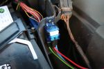
Wiring harness for Hella 4000 Compacts259 viewsWired directly to the battery, all tucked away neatly now but can\'t find the picie
|
|

LTB00304_-_Corroded_fuel_tank_harnes24 viewsLTB00304_-_Corroded_fuel_tank_harnes
|
|

LTB00304_-_Corroded_fuel_tank_harness22 views
|
|
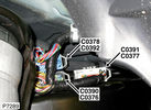
C0390 Chassis harness to main harness215 viewsPart No.: YPC909600
Colour: BLACK
Cavities: 18WY
Harness: CHASSIS HARNESS
Location: Below LH rear wheelarch
|
|
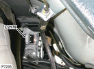
C2178 Module-Parking brake164 viewsPart No.: YPC801020
Colour: BLACK
Cavities: 32WY
Harness: CHASSIS HARNESS
Location: Beneath center of vehicle
|
|
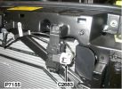
Pollution sensor379 views
|
|
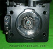
NAS 7 pin + NAS 4 pin Flat Trailer Socket304 viewsThis is the vehicle end of the NAS trailer harness that is located behind the removable plate centered within the rear bumper by the towing loop. Re the four pin flat connector, from the bottom, the exposed bare lower pin is the ground, usually the White wire on a NAS trailer. The next pin up is normally a Brown wire on a trailer and is for the Tail Lights. The third pin, normally a Yellow wire, is the left signal light; the top pin, normally a Green coloured wire, is the right signal light.
Re the round connector, from the notch in the plastic surround, clockwise, the first blade is ignition controlled +12VDC battery power, (only alive when engine running), and on the Land Rover factory harness is an Orange wire; on a NAS trailer, usually Red but perhaps a Black wire.
Next blade clockwise at 3:00 o'clock above, is the Right Turn signal light, a Green wire on the LR harness, and also on a NAS trailer.
At 5:00 o'clock, the next blade is for the Electric Brakes and is Blue on both the LR harness and on a NAS trailer.
The Ground wire is next, White on both the LR harness and on a trailer.
At 9:00 o'clock above, is the Left Turn signal, Yellow on both the LR harness and on a trailer.
The last blade to the left of the line up notch is the Tail Light circuit. On the LR harness, the wire colour is Brown with two White stripes and on a NAS trailer, Brown.
The centre pin is for the Reverse Back Up lights and is Black on the LR harness and often Purple on NAS trailer wiring but can be Black also.
Note that when the socket assembly is installed on the 3, the notch in the plastic surround is on the left - that is rotated 90 degrees anticlockwise to the picture above. In other words, When installed on the 3, the 4 pin flat connector lays horizontal and is located below the round socket.
|
|
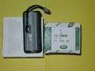
Upper Hatch Release Switch LR Part Number YUZ500020672 viewsThis is the Range Rover Sport switch, Land Rover part number YUZ500020, as it comes out of the box. Note the JAE, (Japanese Aviation Electronics), male wiring connector installed on the end of the power lead.
The rubber cover of the switch is sealed to the plastic body of the switch whereas in the previous switch design, there was no sealing. Also the replaced switch was hard wired into the same harness as the license plate lights - no JAE connector in other words.
|
|
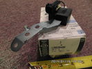
Radio Noise Filter Transmission Electronic Control Unit897 viewsThe jpg shows part number LR020488, a noise suppression capacitor located underneath on a bracket on the right side of the transmission forward of the selector shaft lever. The suppressor is connected to the transmission wiring harness and prevents solenoid operating noise affecting the audio system.
Failure of the capacitor is most often discovered as a result of either black smoke from below and or the blowing of 10 amp fuse F30E located in the engine compartment fuse box. This fuse protects the power circuit to the Transmission Engine Control Unit. When the fuse blows, the engine will still run however you have no gears, hence movement of the 3 is inhibited.
Anything over eight years in service is considered good capacitor life. If the capacitor does fail and fuse 30 blows, a quick fix is just to disconnect the capacitor and replace the fuse.
The capacitor might be missed by the DOT/FCC but the 3 does not seem to mind. With the filter disconnected, solenoid noise might be heard on some radio stations but at least the 3 would be in motion.
|
|
Thread upload2 viewsImage uploaded in thread 123654
|
|
Thread upload18 viewsImage uploaded in thread 114391
|
|
Thread upload16 viewsImage uploaded in thread 114391
|
|
|
|