| Search results - "heated" |
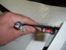
heated seat (base) wiring410 viewsThe Small connector takes the plug from the seat back pad, the larger connector (with red) is fitted into the multiplug casing uder the seat - the male side of this is already pre-wired.
|
|
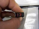
heated seat wiring351 views
|
|

Thread upload9 viewsImage uploaded in thread 151728
|
|
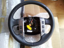
52 viewsHeated Steering Wheel
|
|
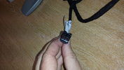
black plug for rear heated seat11 views
|
|
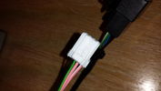
white plug for rear heated seat11 views
|
|
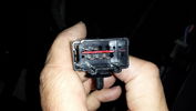
Connector on underseat harness for heated rear seats16 views
|
|
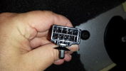
Connector from Main Loom to Heated Rear Seat Harness17 views
|
|
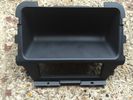
Rear Console trim which i replaced with one with heated rear seats.11 views
|
|

Rear heated seat loom and switches3 views
|
|
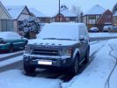
Heated seats, pre-heater, heated screens. Bring it on!262 views
|
|

Alternator and Regulator Wiring Diagrams, TDV6 and petrol V8 and V61973 viewsThis is a three page pdf that shows the alternator and regulator wiring for the petrol V6, petrol V8 and TDV6. The pdf can be either printed or by right clicking on the displayed pdf, rotated as required for viewing.
Of interest is that the regulator gets its instructions primarily from the Engine Control Module (ECM) and only secondarily from the vehicles electrical buss. The conductor from the battery thru the 5 amp fuse F20E is to provide initial power to excite the alternator at startup and then secondarily, to instruct it if the PWM signals were not available. Primary instructions to and from the ECM are thru the two other conductors via a digital like Pulse Width Modulated (PWM) signal.
If F20E, the 5 amp engine compartment fuse box fuse is blown, the red alternator light on the dash will be illuminated. This means that the alternator could be OK, but if the F20E fuse is blown, no electricity will be generated. Hence check the F20E fuse if you get a red ALT light or some indication of the alternator not working.
Regarding operation of the red ALT light on the dash, it is not the regulator within the alternator that tells the red light to illuminate, or not, but instead the ECM. This is the reason the red light does not function in the same manner as with older vehicles. With the 3, sometimes you have illumination and sometimes not depending upon what the ECM is thinking. What this means is that you can have an alternator that is failing but the red light does not illuminate as the ECM is compensating for reduced alternator output - maybe by draining the battery and or cutting back on vehicle electrical loads such as shutting off or cycling the radio amplifier or heated seats.
|
|
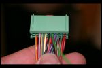
Heated Seat connections in front footwells 3187 views
|
|
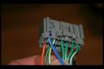
Heated Seat connections in front footwells 2182 views
|
|

FOR SALE - ONE OFF Land Rover Disco 3 37 viewsOne of a kind Landrover Discovery TDV6 HSE LUX Model 5 door automatic 4x4 diesel evo blue. Upgrades: sidesteps, roof rails, privacy glass, front and rear heated seats/elec seats, landrover tv and headphones, 7 seater black leather, piano black dash/steering wheel, built in fridge, 6 disc changer, sat nav and bluetooth, harman kardon premium entertainment pack, by-xenon adaptive headlights , cruise control and front and rear park distance control, panoramic electric glass roof, 22inch alloy wheels, body kit
|
|
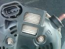
Alternator Plug and B+ terminal910 viewsPictured is the rear of the older Land Rover part # YLE500190 alternator showing the shiny cooling fin of the Regitar VRH2005-142 regulator under.
The first pin in the far left side of the connector is numbered #1 in the LR electrical wiring diagrams and is Battery Voltage Sensing (BVS); the middle pin, #2 receives a Pulse Width Modulated (PWM) signal from the Engine Control Module (ECM), and the right pin, #3 carries a PWM signal back to the ECM. Terminal Pin #2 on the LR wiring diagrams is called Alternator Control or ALT CON; Pin #3 per LR is called Alternator Monitoring or ALT MON.
Pin #1 is similar to what in older designs used to be called A or Batt, but is now called by Denso, S, AS, or Alternator Sensing for this design. Pin #1 also provides power to excite the alternator at startup until the PWM instructions over ride the battery voltage info. Land Rover calls the electronics under the pins a Smart Regulator, ironic, as it has to follow orders from the ECM rather than give the orders - new age thinking I guess. This is different from older design internal regulators that look at just the battery or the electrical buss voltage and then decides itself what to do.
It is almost like we are back to the external regulator designs of old, except that the ECM may decide that instead of telling the alternator to make more power, to load shed, and hence shut down the heated windscreen, seats, or whatever other electrical loads it decides are appropriate. My view is that the "smarts" are in the ECM and that the "regulator" should be regarded if not dumb, then as being a slave to the ECM.
|
|

Thread upload15 viewsImage uploaded in thread 153395
|
|

heated seats57 views
|
|
380 views
|
|

D3 Mirrors and Heated Jets24 views
|
|

Heated Seat Element Wiring - Seat Base47 views
|
|
88 views
|
|

72 views
|
|
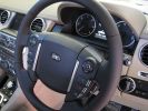
D4 heated wheel tip169 views
|
|
Thread upload6 viewsImage uploaded in new thread
|
|
39 views
|
|
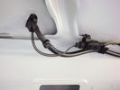
Heated Washer Jets Offside24 views
|
|
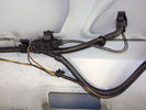
Heated Washer Jets Nearside24 views
|
|
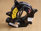
D3 Clockspring Unheated38 views
|
|

128 views
|
|

423 views
|
|
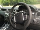
Thread upload12 viewsImage uploaded in new thread
|
|
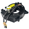
Thread upload2 viewsImage uploaded in new thread
|
|
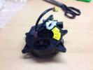
Thread upload19 viewsImage uploaded in new thread
|
|
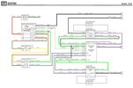
Thread upload20 viewsImage uploaded in thread 178763
|
|

Thread upload4 viewsImage uploaded in thread 143292
|
|
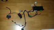
D4 Seat wiring loom9 views
|
|
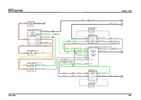
Thread upload19 viewsImage uploaded in new thread
|
|
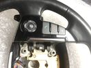
Thread upload8 viewsImage uploaded in new thread
|
|
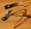
Thread upload9 viewsImage uploaded in new thread
|
|
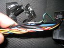
heated seats30 views
|
|
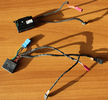
Heated Steering Wheels ECU's93 viewsEarly and Later Heated steering Wheel Control Modules
|
|
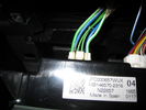
heated seats27 views
|
|
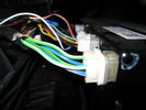
heated seats26 views
|
|
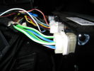
hvac controller120 views
|
|
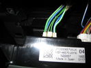
cable onto controller103 views
|
|
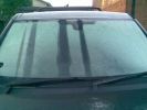
Heated windscreen63 views
|
|
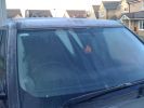
Heated Windscreen Problem327 views
|
|

Black Leather Heated Manual seats6 views
|
|

Black Leather Heated Manual seats6 viewsBlack Leather Heated Manual seats
|
|

Discovery 4 MY2011 Electric Diagram Heated seats29 views
|
|

Power and Heated Seats Electrical Schematic973 viewsThis 6 page pdf shows the wiring for the power adjustment of the front seats and seat heating for all the seats.
Re seat movement or the lack of, not only are there four related fuses, two 30 amp and two 5 amp, (one of each per seat), there are are two separate ground wires, perhaps of more significance than the power, if all movement on either side quits.
|
|

Heated Windscreen Wiring Diagram402 viewsThis single page pdf is the heated windscreen wiring diagram. You can rotate the view by right clicking on the pdf and of course it can be printed out as well.
Relay R208 in the pdf is relay R9 in the Engine Compartment fuse box. Note both 30 amps fuses, F15E and F18E, also located in the Engine Compartment fuse box. If one side of your windscreen does not heat, the problem may be one of the two fuses.
|
|
Thread upload15 viewsImage uploaded in new thread
|
|
Thread upload4 viewsImage uploaded in new thread
|
|

Thread upload4 viewsImage uploaded in new thread
|
|
Thread upload12 viewsImage uploaded in thread 149626
|
|
Thread upload4 viewsImage uploaded in new thread
|
|
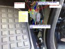
Heated Seat connections in front footwells 1272 views
|
|
heated seats30 views
|
|
heated mat90 views
|
|
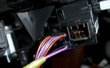
Thread upload2 viewsImage uploaded in thread 44385
|
|
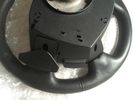
Thread upload4 viewsImage uploaded in new thread
|
|
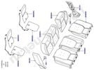
Rear Heated Seat Components4 viewsRear Heated Seat Components
|
|

75 views
|
|
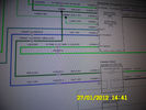
Wiring diagram heated seat 73 views
|
|
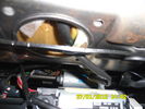
Wiring heated seat70 viewsThis picture is taking from behind the driver seat underneath.. the black cable that goes up in the hole is the wiring for the heat elements. There is a connector on the other end, not visible in this pic.
|
|
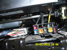
96 viewsConnectors under my driver seat..
Right connector for Heated seat + airbag ++
Left connector for Seat controll I hink
|
|
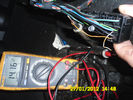
Voltage reading72 viewsHere is the voltage to the heated seat. Engine running. Did not enable heat on the hvac.Why 14v there now?
|
|
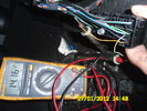
multiplugg under driver seat60 viewsThis picture is takin when diagnosing the heated seat element.
This show that there is 14volts to the elements on these wires.
|
|
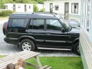
My last car281 viewsDiscovery II GS 7-seat witk side steps, privacy glass, folding mirrors, heated seats, heated screen etc. etc. Oh, and a big lean to the right!
|
|
|
|
|