| Search results - "installing" |
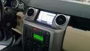
Chinese touchscreen + GPS + USB reader + Bluetooth + DVD32 viewstrying to install this touchscreen
|
|

Air Distribution and Filtering Systems2045 viewsThis is 3 page pdf with coloured drawings of the air distribution ducting for the front air system.
Also included is a sketch of the pollen filter location within the front heater ducting. Note that two types of filters are available: a) the cheaper dust/pollen filter and b), the activated carbon filter that removes smells from the air. Installing the more expensive activated carbon filter means you never smell a cattle truck or chicken farm again. It really works.
|
|

Brake Light Switch, Find, Remove, and Install Instructions 7775 viewsThis is a two page doc outlining where to find the brake light switch, how to remove it, and then install the new one.
Note, do not move the brake pedal when removing or installing the switch. Let the brake pedal hang where it wants to. The switch design is actually cunning, and as such is supposed to make the removal and install fool proof. Hence if you think too much about it, you can wreck the new switch.
If you want to inspect the interior of the switch, wait until you have removed the old switch. You can then just unsnap the blue from the white to get it apart. Inside, the switch is quite simple, (no circuit boards), but it will probably show black dust from failing contacts.
I think the reason the switch fails is that the Normally Open, (NO), contacts of the brake light contacts were made too light to carry the current load for make and break of the tail light filaments. I also think the black dust created then fouls the Normally Closed, (NC), second set of contacts for the ABS circuit. As such, the Normally Closed contacts become intermittent in operation and display as a fluctuating open and closed circuit condition to the ABS system when the ABS should be seeing a steady closed circuit. Hopefully the replacement switch contacts are more robust and may be as I recently replaced my switch again just as a matter of maintenance. While in a redesign, ideally the NC contacts should be sealed or at least separated from the NO contacts, when I inspected the removed switch, this time there was no black dust present.
Probably the removed switch will have a Land Rover oval logo moulded into it, the new one, FOMOCO.
|
|

Installing Ballast Resistor to Vehicle loom162 views
|
|
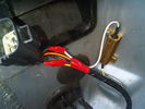
Installing Ballast Resistor to Vehicle loom172 views
|
|
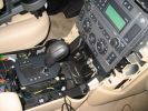
Removing the center console in preparation of installing the Drive+Play components.442 views
|
|

Installing a Fuel Burning HeaterTimer Remote v1-0364 views
|
|

Installing a Fuel Burning HeaterTimer Remote v1-1.pdf419 views
|
|

Thermostat Housing LR005631527 viewsWhen the time comes to install a new thermostat, consider installing the whole housing instead.
Advantages are the thermostat is correctly installed, (not as simple as it should be); you get all new plastic and that is important, plus a new coolant temperature sensor and also a new heater coolant bypass valve, the secret part no one realizes is also within.
The cost of the whole assembly is not much more than the cost of a factory thermostat and the effort to replace all is not as difficult as it might seem.
|
|
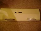
Boot lighting panel, finish side up 307 viewsThe above jpg shows the two 15 LED light assemblies as well as the SPST rocker switch mounted beside the W5W Land Rover supplied light.
The reality is that with the recent development of LED lighting that can replace a W5W T10 bulb, one can almost achieve the same results just by installing a LED bulb within the factory light.
|
|

Land Rover Brake Light switch XKB5001102675 viewsThis is what the switch looks like when removed from the parts box. Note that the plunger is recessed back into the body and when installing, the process of rotating the switch body 1/4 turn anticlockwise releases the plunger so it pops longer and engages the brake pedal. If you look down on the plunger you can see curved slots where the rotation takes place.
Do not try to rotate the new one - play with the one you remove. Also do not press on the brake pedal when removing or installing as you will damage the plunger - this is one of the reasons the plunger is retracted into the body for installation. It is also for this reason that if you try to confirm the operation of the switch contacts with an ohm meter by pressing the plunger, the switch will appear not to function as one might anticipate. Have faith, the switch will however, once installed and the plunger is in full motion.
|
|
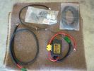
Traxide SC80-LR644 viewsKit -- cable was 6 feet short. Check to ensure the length is adequate prior to installing it.
|
|

CounterAct LT-2 Install Instructions169 viewsThese are the instructions for installing the CounterAct coupler pads (2) and the power supply.
|
|
|
|
|
|
|