| Search results - "lower" |
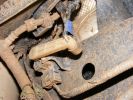
650 viewsNote blue rubber collar to hold lower part of control rod in arm.
|
|
381 views
|
|
381 views
|
|
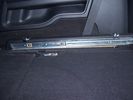
Side runner in position showing front lower than rear.29 views45%
|
|
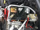
Wiring334 viewsThis is the final wiring configuration. It shows the dual battery wiring, 75A wiring run to the boot, the winch and in the lower right you can see a few turns of coax with a snap on ferrite near the base of a VHF Antenna.
|
|
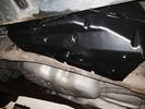
air compressor cover, lower1 viewsImage uploaded in thread 177818
|
|
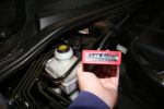
TT Box Jumpers134 viewsEasy to remove cover and setting the jumpers to either higher or lower settings
|
|
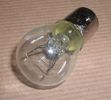
Land Rover Stop Tail Light dual filament bulb nominal 12 volt 21 / 5 watt filaments1412 viewsThis is the Land Rover part number 264590 dual filament bulb, (P21/5), that inserts into the upper two tail lamp receptacles. In the upper one, both filaments function, in the lower one, only the 5 watt tail light filament functions.
I regard it as not a good practice to routinely switch bulbs when the tail light filament, (5 watt), burns out on the lower bulb. The broken filament can jiggle over onto the brake light filament, (21 watt), and short the circuit to ground or something else not predicable.
There are also arguments to say that quality control is better on the Land Rover marketed bulbs than say far east sourced bulbs. Filament construction, and hence resistance can vary and mislead the current sensing circuits monitoring the signal light systems. Also when the bulbs are properly installed, all filaments should be standing vertically and not at any slope.
These are the sort of obscure circumstances that can lead to false trouble messages on the display, dropping to the stops, and subsequent concerns - all over a tail/signal light bulb.
For example, the filament life of both the tail light and the brake light filaments in the P21/5 bulb is significantly less than the USA common 1157 dual filament bulb, (1000/250 vs 5000/1200 hours); brightness in the P21/5 is a bit more, (3cp/35cp vs 3cp/32cp where cp is candle power), but current consumption is oddly less, (0.44a/1.86a vs 0.59a/2.10a where a is amps). It is the quest for efficiency vs maintenance trade off.
|
|

Thread upload3 viewsImage uploaded in thread 180827
|
|

Rear Area Climate Control System1140 viewsThis 14 page pdf describes how the rear heating AC system is supposed to operate in conjunction with the front system.
The air transfer ducts are shown as coloured sketches as is the air flow within the rear blower setup.
|
|
Thread upload36 viewsImage uploaded in thread 102519
|
|
Thread upload40 viewsImage uploaded in thread 102519
|
|

Thread upload6 viewsImage uploaded in new thread
|
|
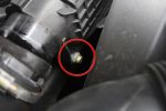
Air Box Lower Securing Bolt1062 viewsThis bolt must be undone in order to remove the air box. It is long and tricky to get out and could be dropped easily.
|
|
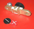
Battery Disconnect side post with + & - caps under view738 viewsThe upper and lower pieces of metal are clamped together but electrically seperate from each other. The connection between the two pieces is via the threaded part attached to the knob. When the knob is turned tight, current will flow between the two sections of metal.
|
|
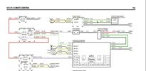
Thread upload1 viewsImage uploaded in thread 198400
|
|
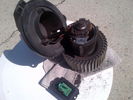
Thread upload117 viewsImage uploaded in thread 69791
|
|
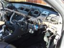
where this bit go155 viewsproject 5ser heater blower..... joy
|
|
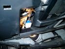
Brake Switch Visible thru Opening4933 viewsThe blue and white bit is the switch; the sort of gold appearing box,(it is really black), you will not see in your 3 as it is a Smooth Talker brand amplifier for my Blackberry phone antenna. This install is detailed in the SmoothTalker phone antenna section of my gallery.
One way to remove and install the switch is to lower the "horizontal" panel above the brake pedal as shown where the flashlight head is located. To actually remove the switch, you slide your hand thru the gap and rotate the switch clockwise 1/4 turn while watching thru the rectangular opening. Installation of the new switch is the reverse of above - 1/4 turn counterclockwise.
Before you remove the switch, note its orientation - horizontal with electrical wires to the left. That is the way it should look after replacement as well.
The second time I replaced the switch, I did it all thru the rectangular opening and did not remove the horizontal panel - that is experience helping out.
The knee kick you have to remove regardless. It is sort of hinged at the bottom so you just pull at the top and sort of rotate the knee panel and then pull upwards for two plastic "fingers" to clear the slots they reside in.
|
|
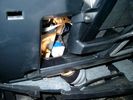
Smooth Talker Amplifier Box mounted below near steering column.179 viewsThe gold look box due to the lighting, (actually black), is the antenna amplifier located near the steering column. It can be put anyway but this seemed an OK location as I ran the antenna connector cable rearward from here to the back corner of the 3 and then up to the underside of the roof glass at the rear. The blue/white thing is the brake light switch that often must be replaced. See the Brake Light Switch file within this Gallery regarding the switch replacement.
|
|

C Pillar Lower Trim Removal406 views
|
|

Changing a Lower Tailgate Stay Cable.pdf8 views
|
|

TDV8 to Date248 views2007 (57) TDV8 HSE
Mods:
BAS mapped.. oh yeah..
Colour coordinated lower sills,Java handles, supercharger vents and grill
Hawke smoked repeaters
Halo style HD LED rings in headlights
22" supercharger style diamond cut alloys
2011 LED rear lights
|
|
147 views
|
|

40 views
|
|
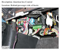
D3_CJB_lower_connections_inc_for_LR_spotlights_C058023 views
|
|

Seat base electrics cover39 views
|
|

Front seat lower cover removal replacement43 views
|
|

Lower Seat Cover and T40 Torx bit for seat base removal45 views
|
|

Diesel - Ethanol co-fuel Paper109 viewsInteresting read - one local authority (Redland Shire Council) has 180 vehicles on trial and is pleased with the results; more power, engines run cooler; lower emissions including reduced smoke and it is a renewable resource to boot!
|
|

Thread upload2 viewsImage uploaded in new thread
|
|

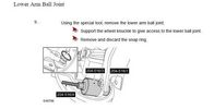
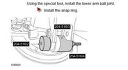
Lower arm fitting instruction152 views
|
|

66 views
|
|

Thread upload5 viewsImage uploaded in thread 143660
|
|
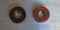
lower roller bearing RHS, upper on LHS49 views
|
|
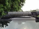
Wind Deflector for Rack14 viewsRecognise this part? Its the lower front recovery point cover. Installed upside down to silence the wind "drone" on the roof rack - works a treat!
|
|
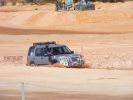
254 viewsD3 - we entered pit 1 a little slower than the Jeep!
|
|

rear vents trim178 viewsto remove just pull starting from the lower part
|
|
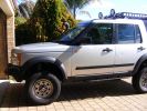
411 viewsLower front bib is removable via two bolts, for increased approach angle
|
|

Another view50 viewsA view of the general area showing the damaged part, lower centre. The second occurrence shows similar damage.
|
|
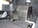
Left hand side of internal 40 Litre water tank161 viewsView from floor looking towards tank. Top white cover is 50mm plastic pipe cap. It protects the tank vent valve. Dispensing hose is at lower corner of tank
|
|
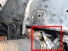
Further detail of attachment of the winch hoses to power steering system140 viewsThis is under the right (looking forward) lower plastic radiator cover.
|
|
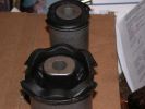
Lower Control Arm Bushings LR3 USA104 viewsLower Control Arm Bushings LR3 USA
|
|

78 viewsJust after the first river crossing there is a sunny field of blue flowers.
|
|

flower109 views
|
|

Thread upload2 viewsImage uploaded in new thread
|
|

Thread upload7 viewsImage uploaded in new thread
|
|
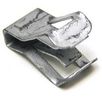
FYC50004082 viewsLower dash retaining clip
|
|
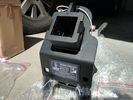
Rhino Tow Loop Hitch263 viewsThis is a receiver end view of the Rhino Hitch that ties to the factory tow loop. In addition to improved strength, it does not reduce ground clearance as does the factory style when installed.
Land Rover in early advertising videos when the 3 first came out showed the D3 hanging from a crane via the frame. The intent was to show how strong the frame is and by inference, the rear tow loop, specifically noted as being good for 6 tonne. The video ends before anything dropped or was lowered back to the ground, so one of course does not know for certain. The Rhino Hitch design however picks up on the apparent evidence of strength and certainly the additional clearance.
|
|
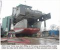
Messing with boats112 viewsShows our 300t capacity Lift System holding up an 80 tonnes module as the hull is winched underneath for final lowering and welding together.
|
|
Lower front arm bushing71 views
|
|
Lower front arm bushing68 views
|
|
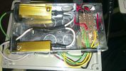
Underside137 viewsThe underside of the inside box. Resistors are 6 ohms with a power rating of 50w, don't be tempted to get the lower power rating.
|
|
34 viewsWhen adding two single DIN supports together, you get quite a gap at the front.
This gap was way too much in my case, as it turned out that both supports started to bend when putting them both in the facia. Not that good, so I decided to cut off the upper part of the lower DIN support.
|
|

passenger side cup holder - Blank (SE model and lower)277 views
|
|
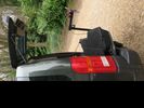
"4x4" with lower tailgate down32 views
|
|
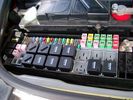
Picture of the engine compartment fuse panel5752 viewsEngine compartment fuse panel located near the battery. This is where F3E, (5 amp), F26E, (20 amp), Fuseable link 10E, (60 amp) and Relay 7E, the now upgraded 70 amp air compressor motor relay, part number YWB500220, (E is for Engine compartment fuse box), are all located. Fuse F35P, (5 amp), is inside the Passenger compartment behind the lower glove box door.
To keep the suspension from going down to the stops when driving, (or parked), it appears that it is only really necessary to remove F26E to depower the exhaust valve and generally keep all the valve block solenoid valves in a closed position trapping whatever air is within the air springs. F3E gets its power thru F26E, so when F26E is removed, the F3E circuit is automatically de-powered. F35P is more interesting in that battery power goes thru the ignition switch and F35P and then into the air suspension control unit. Apparently however, if F26E is removed, removing the F35P is not needed even when the engine is running.
With all fuses still in, if you have a problem, in practice, ideally, the compressor still works and will raise the 3 to an appropriate height. If so, one can then shut the engine off and allow the computers to go to sleep and then you remove the fuse(s). In actual practice, it seems that one need only pull the F26E fuse and can do so with the engine running. All the same, one might consider that the 3 is first a mobile computer, and secondly a 4x4. Computers prefer to go to sleep before the plug is pulled on them, however given that F26E circuit is always alive, then the computer never sleeps. With the fuse(s) pulled, and if you are still up, you can now be a 4x4 instead of a low rider. The whole purpose of the fuse pulling exercise is to depower the one and only system exhaust valve that is physically located within the compressor unit, (to keep it from opening), and secondarily to keep closed the four air spring solenoids within the block valves. This also shuts the air compressor down and stops the air compressor from making air even if the compressor is still good. That is why you initially need the fuse(s) in to allow the compressor to make air if it can.
|
|

Switch is blue colour thing thru the rectangular opening.3149 viewsThe blue coloured plastic bit thru the rectangular opening is the brake light switch. The fist time, I found it easier remove the switch by dropping the horizontal plastic panel, (two screws), and then slipping my hand in and rotating the switch clockwise 1/4 turn. The second time, I was able to remove the switch thru the rectangular opening and did not need to remove the horizontal lower panel. Obviously, I had to remove the sloping knee pad panel, (note sort of hinged at the bottom so pull back from the top.)
Regardless, do not touch the brake pedal - just let it sit where it wants to. One has to first remove the angled knee pad panel that sits under the steering wheel. It can be pulled from the top corner at the door side. Pulling releases a pair of those U shaped metal clips that LR loves so dearly. You have to pull quite hard. The bottom is held by a couple of plastic fingers in a couple of slots so you pull at the top till the two clips release and then rotate the panel and pull upwards a bit.
To remove the switch, you rotate it clockwise and pull outwards. Rotating the switch clockwise automatically retracts the plunger back into the switch body away from the brake pedal arm.
Similarly when you install the new switch, the required 1/4 turn anti clockwise rotation action releases the plunger so it lays up against the brake pedal arm and at the same time, secures the switch in place.
To remove the electrical wires, the switch will drop below the horizontal pad and hang from the wires so unclipping the electrical connector plug is fairly easy to do.
|
|
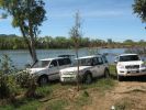
Beside lower Ord River, WA, Aust133 views
|
|
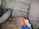
plastic inspection panel lower right weelarch45 views
|
|

IC hose lower clip46 views
|
|
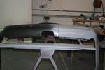
Rear Bumper Showing Lower Fixing Points82 views
|
|
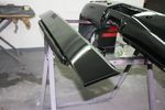
Lower Tailgate Trim Lacquered106 views
|
|
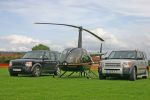
CALENDER ENTRY 2010268 viewsTaken at Nailsea flower show. I drove my disco there then Frapp took me to the airport to collect the helicopter. I flew the choper in and Frapp drove back there. Guess who arrived first!
|
|

Old front lower wishbone24 views
|
|

Img 4103 viewsUpper glove box removed. Here you can see the power supply for the lower glove box light. Simply use this as your power supply for the new upper light.
|
|

Modified Thule 9705 bike carrier50 viewsBar has been moved up above the tow ball and the lower fixing replaced by nuts and bolts.
|
|

UHF Antenna Mount384 viewsView from underside of bonnet. The lower half of the mount is folded from stainless steel and bolted through an exisitng oval shaped hole in the bonnet. This hole is throught the heavy steel plate that the bonnet hinges bolt to - not just the aluminium panel. A specially machined rectangular nut was made to pass through the oval hole, rotate 90 degrees and then stopped from turning by a slight shoulder on the nut.
|
|
88 views
|
|

Key in Ignition Electrical Wiring Diagram1043 viewsThis shows the key in ignition wiring, (LGW, 1.5D), running from the key lock cylinder to the Central Junction Box, (CJB), thru 5 amp fuse F40P, located in the fuse box behind the lower glove box door.
You can remove the 5 amp fuse and the good news is that the ignition chime will not sound any longer; the bad news is that a bunch of other circuits that rely on knowing if the key is in or out no longer work.
Also note the Transponder Coil D219 reference.
|
|
![Filename=kit616-rear-lower-arms-with-fitting-kits-discovery-3-4-air-suspension-only-1108062-p[ekm]270x210[ekm].jpg
Filesize=18KB
Dimensions=270x210
Date added=13.Jun 2019 kit616-rear-lower-arms-with-fitting-kits-discovery-3-4-air-suspension-only-1108062-p[ekm]270x210[ekm].jpg](albums/userpics/33392/thumb_kit616-rear-lower-arms-with-fitting-kits-discovery-3-4-air-suspension-only-1108062-p%5Bekm%5D270x210%5Bekm%5D.jpg)
Thread upload1 viewsImage uploaded in new thread
|
|

Thread upload0 viewsImage uploaded in new thread
|
|
Thread upload4 viewsImage uploaded in new thread
|
|
Thread upload4 viewsImage uploaded in new thread
|
|
Thread upload4 viewsImage uploaded in new thread
|
|

Littelfuse Add-A-Circuit MINI and ATO style data sheet148 viewsPDF from Littelfuse showing both the MINI and ATO style of fuse holders. The 3 uses the MINI size of fuse. The MINI Add-A-Circuit can be inserted in place of one of the existing fuse panel MINI fuses. The removed fuse is then inserted into the lower slot of the Add-A-Circuit and a second fuse in the second slot to protect the device that you are adding. The Add-A-Circuit is designed for a max of 10 amps on the second load, and I guess maybe the original circuit as well.
|
|

Front suspension lower arm599 views
|
|

166 views
|
|

Thread upload19 viewsImage uploaded in thread 127167
|
|
Thread upload4 viewsImage uploaded in new thread
|
|
Thread upload12 viewsImage uploaded in new thread
|
|

192 views
|
|

Thread upload29 viewsImage uploaded in thread 108698
|
|
Thread upload18 viewsImage uploaded in thread 122062
|
|
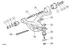
lower arm front suspension73 views
|
|

Thread upload2 viewsImage uploaded in thread 204346
|
|
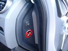
Air Suspension ECU Fuse 35P cut off switch.3802 viewsThis shows the SPST rocker switch mounted in the blank plate installed in lieu of a manual passenger side air bag shut down switch - now automatic via passenger seat pressure switch. Fuse 35P (5 amps) is located in the interior fuse box behind the lower glove box and protects the ignition power supply to the Air Suspension ECU. When the SPST switch is moved to the OFF position, the RAISE /LOWER switch on the centre console is not powered, and hence does not function. As such, some signals from the wheel height sensors and CPU are ignored. By itself however, removing F35P will probably not stop the 3 from self dropping, particularly after the engine is turned off.
Fuse F3E, (5 amps), located in the engine bay fuse box by the starting battery protects the circuit that provides feedback to the Air System ECU indicating that the Compressor Relay has successfully operated and that the Air Compressor is or should be operational, can also be removed, (but is probably not totally necessary), as it gets its power thru F26E. Hence Fuse F26E, (20 amp), also located in the engine compartment fuse box is the fuse that must be removed. This fuse protects the circuit that provides full time battery power to the Air System ECU. When in place, current thru the fuse powers the periodic re-levelling action, (usually lowering a bit with that brief air release noise), that often occurs when the vehicle is parked and the engine is off.
Removing F26E fuse will stop the auto levelling action and also inhibit any other down to the stops signals, (engine running or not). When F26E is removed, no power can flow thru to F3E, hence removing F3E is more for insurance than an absolute requirement. The same with F35P, removing F26E removes primary full time power from the Air Suspension ECU, and hence removing the F35P fuse should not really be required either as long as F26E has been removed.
|
|
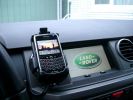
BlackBerry Tour 9630 mounted on air vent264 viewsThe antenna amplifier is mounted lower near the steering column. The amplifier box is painted black but looks sort of gold coloured due to the lighting in the other jpg showing the amp located under/near the steering column.
|
|
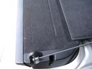
Flexible wire rope fishing leader 0.032" diameter exiting carpet 1931 viewsThis is all you see of the completed mod.
The short little angled "line" about an inch long that looks like a piece of debris and is located a few inches "above" the support cable is actually the wire rope release cable exiting from under the carpeted lift gate cover.
I drilled a very small hole in the carpet and pushed the 0.032" diameter release wire thru and then slipped the loose end under the black plastic.
To release with the lift gate etc closed, from the inside, just pull the loose end free from under the black plastic and gently pull wire about 5mm, (1/4"), and the upper door catch should release. You will have to manually push the upper door out wards to actually effect opening, but you will already be inside the rear cargo area so that part is easy to do.
The assumption is that the lower door latch still works electrically and hence, the lower lift gate half will open as normal by pressing the usual button on the top left of the lower door half.
|
|

Carpet Panel Removed showing Bass Speaker and Dust Shield 1722 viewsSomething is wrong with the orientation, however this shows what you see when the carpet is removed.
The dust shield, (under which the actuator is located), in the picture is as yet uncut. The white bit is the underside of the plastic lower lift gate carpeted cover panel.
The round thing is the woofer speaker for the Harmon Kardon radio. When the radio is working, one can see the speaker moving, but not much bass sound actually seems to emanate from the speaker.
|
|
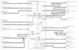
Power Window Circuit centered on Central Junction Box (behind glove box fuse panel)726 viewsRelay 143, the power window relay, and most other relays and FET's as well are built into the back of the passenger side behind the lower glove box fuse panel.
As such, the relays etc are not removable, jump-able, or serviceable.
|
|

LR3 Sparkle Silver 6 spoke Wheel Cromodora of Italy 19 inch x 8 ALY72191U1106 viewsThese are the standard equipment 19" wheels on the 2005 LR3 HSE. The wheels are Made in Italy by the Cromodora company. Each are rated at 940 kg (2,072 pounds) and have an offset of 53 mm positive, (53P or +53).
I mention the 940 kg load rating as that is about the heaviest rating of any Land Rover product. The RRS and RRHSE both have lower ratings. What this means is that while a wheel from a Range Rover may physically fit, it probably does not have the brute strength of the factory spec Land Rover 3 wheel. There is no Land Rover product heavier than the 3, hence the 3 wheel design spec is the heaviest of the bunch.
|
|
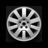
LR3 Sparkle Silver 10 spoke Wheel Cromodora of Italy 18 inch x 8 ALY72190U725 viewsThese wheels are factory standard on the 2005 LR3 SE and Made in Italy by the Cromodora company. Each wheel is rated at 940 kg (2,072 pounds) and has an offset of 53 mm positive, (53P or +53).
I mention the 940 kg load rating as that is about the heaviest rating of any Land Rover product. The RRS and RRHSE both have lower ratings. What this means is that while a wheel from a Range Rover may physically fit, it probably does not have the brute strength of the factory spec Land Rover 3 wheel. There is no Land Rover product heavier than the 3, hence the 3 wheel design spec is the heaviest of the bunch.
|
|
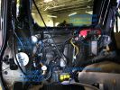
a few items being built in behind cover panel.435 viewsred inverter will have fluch mount plugs, air outloet will be flush, guage with window in lower pop-panel and switches and fuses for all rear items behind popout panel.
12v sockets being added as well, high and low.
|
|

LR3 AJV8 block heater location631 viewsThis 1 page pdf shows the screw in block heater location as related to the lower left side of the engine block.
|
|

Horn Wiring Circuit LR3575 viewsThe is the wiring diagram for the dual horn circuit.
The Horn Relay, (R133), is not a big black thing hidden somewhere but instead what is called a FET, (and it is hidden)!
This is a Field Effect Transistor that is built into the circuit board that is mounted to the back of the fuse box that is located behind the lower glove box door on the passenger side of the 3. The related 15 amp fuse, 12P, is mounted in this fuse box and is often called F12P, where F is for fuse, and P is for Passenger compartment.
This is to help differentiate from another fuse and relay box, (the usual kind), that is located beside the starting battery in the Engine compartment. FxxE is often used in the naming of those fuses.
|
|

Stop Light Lamp Circuit pdf2460 viewsThis pdf shows the brake light circuit for the NAS LR3.
Note that power for the brake light bulbs can come either thru the brake light switch power feed /contacts plus also from the Hill Decent Control, (HDC), system relay located within the Central Junction Box, (CJB) - yes two separate sources of power for the brake light bulbs. This would tend to explain how a brake light circuit concern shows up as a hill decent fault message; also why lesser vehicles without hill decent braking mechanisms, (HDC), never display this sort problem when a brake light bulb or switch acts up. You never have a problem related to a system that does not exist.
Additional evidence of the relationship of the HDC and the tail light circuit is demonstrated by when the HDC actually acts to slow the 3 down, the brake lights automatically illuminate even if the slowing action was merely retarding the engine speed or shifting to a lower gear, (in other words, no foot on the brake pedal).
There is also a tie in to the Cruise Control and hence a failing brake light switch can affect cruise operation or just create false Cruise Control messages. To further complicate the issue, while there are no messages generated, operation of the radiator electro viscous fan can also be negatively affected by the fouled set of secondary contacts within the brake light switch. This is all because the NC contacts within the brake switch send misleading messages to the ECU.
While the ground wire design is similar to other vehicles, note the grounds for the brake light filament and the reverse light filament are common on each side. That means that if one has a non functioning brake light on one side, the reverse light may not also work or that some problem with the reverse lights could back feed into the brake lights. This situation while unusual, can result when grounds are corroded probably due to swimming in rivers and creeks or just routine driving in a marine environment.
|
|

LTB00118 - Technical Bulletin - Removal and install Front Lower Suspension Arm106 views
|
|

LTB00133 - Technical Bulletin - Low Engine Coolant Level Switch - Lower Level Service Part Availability79 views
|
|

LTB00172 - Technical Bulletin - Transmission Input Shaft Seal - Lower Level Service Part Availability and Repair Procedure65 views
|
|

LTB00328 - Technical Bulletin - Rear Door Window Regulator - Lower Level Service Repair125 views
|
|

LTB00360 - Technical Bulletin - Front Seat Rail - Lower Level Service Repair122 views
|
|

88 views
|
|
Motor Blower Fan19 views
|
|

Desert Wild Flowers after rain201 views
|
|

VUB501210 lower bumper brackets94 viewsVUB501210
|
|

90 tonnes Transformer - Tooley Street84 viewsOur 300t Lift System with a 90 tonnes transformer hanging from it just before lowering 9 metres into a basement.
|
|
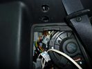
rear socket install1386 viewsTraxide rear socket installation, alternative location. These holes must be precisely in this location because there is little clearance to the right of left due to the blower motor and hoses, etc.
|
|
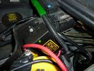
Traxide SC80-LR mounted591 viewsA close up showing the angle, mounting bolt. Only a single top bolt can be used, there are metal lines behind the lower bolt hole.
|
|
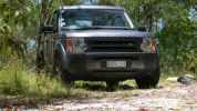
Turn around area near Pyrocarpa Flora Reserve117 viewsApproximately 29ºS, 153.21ºE (did not observe the Eucalyptus pyrocarpa flowering though).
|
|
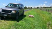
South of Coraki124 viewsPatch of flowers observed on side of road. Don't know whether they were planted or came up naturally. No other patches visible along either side of the road.
|
|

Coraki - flowers on side of road south of Coraki117 viewsJust one small patch of them and no others within sight.
|
|

Horror. The jack tilting over. If I hadn\'t lowered the car, it would have fallen.365 views
|
|
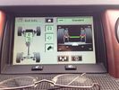
Display showing suspension lowering!23 views
|
|
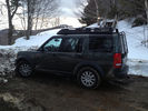
Killington VT 201335 viewsParked at lower driveway
|
|
Wild Flowers343 viewsWreath Flowers
|
|
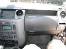
213 viewsThe start. I plan to place all the electronics into the lower glove box.
|
|
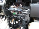
277 viewsHere is the center console with the support pulled away. You can see the wiring for the HD and XM radios working their way through the console and over to the lower glove box.
|
|
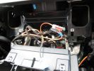
278 viewsClose up of the cavity for the Nav screen. Here you can see the XM Satellite receiver antenna cable snaking across. It\'s the thin wire not bundled to anything. In the lower corner you can also see the power cable going to the glove box.
|
|
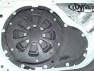
Pioneer TS-SW1041D 10" sub installed120 viewsAfter cutting off the factory sub mount studs, it took ages to bash the indents. To gain more space behind the driver - I changed the driver\'s side license plate from plastic push in lug - to stainless bolt with nyloc nut. Cr@ppy paint job in wrinkle-finish - all I had on hand at the time. Sealed and treated lower tailgate with Dynamat.
|
|
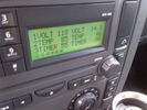
Voltage Display Page Radio Head Unit 118 14.2835 viewsThis shows the voltage/temperature/timer display page within the 6CD-465 radio head. There is a second file within this album, a doc file, that outlines the procedure to access the diagnostics.
The 14.1 volts number was the approximate vehicle system voltage with the engine running; the 118 number infers 11.8 volts which is the low power infotainment system shutdown cutoff voltage. The factory default setting is 135 or about 13.5 volts. By holding the keypad 1 button down, the 3 digit volts numbers will decrease 001 at a time until the keypad 1 button is released. Decreasing the number from 135 to some lower number should increase the time the system will remain on with the engine off.
The TEMP numbers refer to Fuel Burning Heater, (FBH), temperature values. 85 is apparently a high limit and 46 was the number when the jpg was taken. This number varies and given that there is no diesel fueled FBH in our NAS petrol engine vehicles, what the value refers to is unclear. The TIMER numbers also relate to the diesel fuel burning engine heater and perhaps make more sense being 00.
|
|
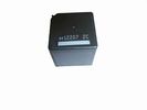
Front Blower R16 relay, part number YWB500060473 viewsThis is the front fan relay located in the engine compartment fuse box. It should be replaced and installed new when a new fan is installed.
|
|

Removal of C-Pillar Lower Trim84 views
|
|

598 views
|
|

Replacing the blower motor572 viewsThis is a 6 page pdf with regards to replacing the HVAC blower fan and the associated fan speed module in a LHD North America spec LR3. The fan can be replaced from below and it is not necessary to pull the dash apart.
|
|

Thread upload0 viewsImage uploaded in thread 205707
|
|

Thread upload0 viewsImage uploaded in thread 205707
|
|

91 viewsThe river next to the field of blue flowers. We ended up crossing this river dozens of times and eventually drove in it it for more than a mile.
|
|
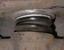
35 views
|
|
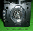
NAS 7 pin + NAS 4 pin Flat Trailer Socket304 viewsThis is the vehicle end of the NAS trailer harness that is located behind the removable plate centered within the rear bumper by the towing loop. Re the four pin flat connector, from the bottom, the exposed bare lower pin is the ground, usually the White wire on a NAS trailer. The next pin up is normally a Brown wire on a trailer and is for the Tail Lights. The third pin, normally a Yellow wire, is the left signal light; the top pin, normally a Green coloured wire, is the right signal light.
Re the round connector, from the notch in the plastic surround, clockwise, the first blade is ignition controlled +12VDC battery power, (only alive when engine running), and on the Land Rover factory harness is an Orange wire; on a NAS trailer, usually Red but perhaps a Black wire.
Next blade clockwise at 3:00 o'clock above, is the Right Turn signal light, a Green wire on the LR harness, and also on a NAS trailer.
At 5:00 o'clock, the next blade is for the Electric Brakes and is Blue on both the LR harness and on a NAS trailer.
The Ground wire is next, White on both the LR harness and on a trailer.
At 9:00 o'clock above, is the Left Turn signal, Yellow on both the LR harness and on a trailer.
The last blade to the left of the line up notch is the Tail Light circuit. On the LR harness, the wire colour is Brown with two White stripes and on a NAS trailer, Brown.
The centre pin is for the Reverse Back Up lights and is Black on the LR harness and often Purple on NAS trailer wiring but can be Black also.
Note that when the socket assembly is installed on the 3, the notch in the plastic surround is on the left - that is rotated 90 degrees anticlockwise to the picture above. In other words, When installed on the 3, the 4 pin flat connector lays horizontal and is located below the round socket.
|
|

Thread upload8 viewsImage uploaded in new thread
|
|
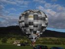
My Edit - Hot air balloon taking off from Bakewell on the 19-09-1053 views
|
|
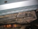
Rear N/S Lower Mounting Holes158 views
|
|

Thread upload16 viewsImage uploaded in new thread
|
|
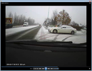
car cleared of snow11 viewsMaserati pulling out of gym car park with snow all over, only cleared parts of side window by lowering them and raising back up 4" .
from only drivers side quick wipe down and rear postbox size clear spot in centre
|
|
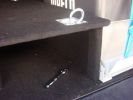
Spare wheel lowering tool98 viewsHidden below is the adapter from the 22mm bolt head to a 1/4 inch drive
|
|

365 views
|
|
Front Grill Removal320 views
|
|
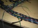
Wire swapping88 viewsPulling out the old cut wires while routing in the new, you can see some already done in the lower loom body. The loom will be re wrapped at the end so i only need to hold it in place periodically at this point.
|
|
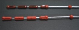
TDv6 Oil dip stick275 viewsPhoto shows oil level on rear stick (cleaned front stick). Note that diesel oil when fresh may not be black like the sample shown (car had travelled 5 000km on delivery oil). You can see small indentations in both sticks. This is where I observe the current oil level. Note also the two arrows at either end of the red plastic indicators showing lower and upper limits (I do not know what the red ball is for however - it just may be a guide.)
|
|
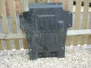
Lower engine bay tray313 viewsLower engine bay tray, 2006 Disco3 TDV6. Needs removing to gain access to sump drain plug.
|
|

VUB501210 lower bumper brackets112 viewsVUB501210, brackets, bumper
|
|
|
|
|
|