| Search results - "module" |

0000 LR Bluetooth dealer Kit install instructions1583 viewsThis 17 page pdf is mostly a series of pictures showing how to install the original Land Rover dealer installed Bluetooth kit for circa 2005 / 2006 three's. Also included are three wiring diagrams sheets related to the pairing code 0000 Bluetooth install.
This pdf is useful if you are now removing the 0000 kit to install the optical 2121 MOST D4 module, an easier install than the 0000 kit ever was.
|
|
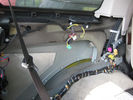
pdc module in rear passenger side43 views
|
|

pdc module in rear passenger side37 views
|
|
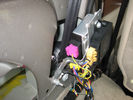
pdc module in rear passenger side38 views
|
|

Parking module120 views
|
|

1 ICE Loom - Behind boot trim drivers side. TMC and Nokia modules91 views
|
|
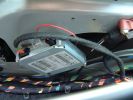
1 TMC - mounting TMC Module91 views
|
|

seat air bag module104 views
|
|
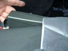
2 Nokia - Location of Nokia Module on trim71 views
|
|

most connector with 4 pin plug for usb/ipod module 54 views
|
|
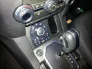
ANITAS D4 suspension module remote controller65 views
|
|
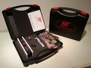
ANITAS suspension module kit73 views
|
|
Driver Seat Memory Module2 views
|
|
FBH Remote Module3 views
|
|

C0506R56 viewsDescription: ABS module
Location: Rear of engine compartment - driver side
|
|

Air suspension Control Module99 viewsDescription: Air suspension Control Module
Location: RH 'A' post
Part No.: YPC500830 Colour: NATURAL Cavities: 20WY
Harness: CABIN HARNESS
|
|

Alternator and Regulator Wiring Diagrams, TDV6 and petrol V8 and V61973 viewsThis is a three page pdf that shows the alternator and regulator wiring for the petrol V6, petrol V8 and TDV6. The pdf can be either printed or by right clicking on the displayed pdf, rotated as required for viewing.
Of interest is that the regulator gets its instructions primarily from the Engine Control Module (ECM) and only secondarily from the vehicles electrical buss. The conductor from the battery thru the 5 amp fuse F20E is to provide initial power to excite the alternator at startup and then secondarily, to instruct it if the PWM signals were not available. Primary instructions to and from the ECM are thru the two other conductors via a digital like Pulse Width Modulated (PWM) signal.
If F20E, the 5 amp engine compartment fuse box fuse is blown, the red alternator light on the dash will be illuminated. This means that the alternator could be OK, but if the F20E fuse is blown, no electricity will be generated. Hence check the F20E fuse if you get a red ALT light or some indication of the alternator not working.
Regarding operation of the red ALT light on the dash, it is not the regulator within the alternator that tells the red light to illuminate, or not, but instead the ECM. This is the reason the red light does not function in the same manner as with older vehicles. With the 3, sometimes you have illumination and sometimes not depending upon what the ECM is thinking. What this means is that you can have an alternator that is failing but the red light does not illuminate as the ECM is compensating for reduced alternator output - maybe by draining the battery and or cutting back on vehicle electrical loads such as shutting off or cycling the radio amplifier or heated seats.
|
|

Entertainment System Wiring Diagrams2303 viewsThe 12 page pdf has the wiring diagrams for the low and high line "radio" and various components such as the amplifier, phone modules,NAV display, antennas and satellite radio and TV.
|
|

9 views
|
|

Fibre Optic MOST bus plus CAN, LIN, GVIF and SLIN buses1523 viewsThis 7 page pdf introduces the fibre optic MOST bus, (the orange coloured cables), the two high and medium speed CAN buses, the Gigabyte Video InterFace, Local IntercoNnect, and Security Local IntercoNnect buses.
|
|
41 views
|
|

Thread upload46 viewsImage uploaded in new thread
|
|

Thread upload0 viewsImage uploaded in new thread
|
|

Audio Connectivity Module fitting instructions740 views
|
|
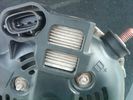
Alternator Plug and B+ terminal910 viewsPictured is the rear of the older Land Rover part # YLE500190 alternator showing the shiny cooling fin of the Regitar VRH2005-142 regulator under.
The first pin in the far left side of the connector is numbered #1 in the LR electrical wiring diagrams and is Battery Voltage Sensing (BVS); the middle pin, #2 receives a Pulse Width Modulated (PWM) signal from the Engine Control Module (ECM), and the right pin, #3 carries a PWM signal back to the ECM. Terminal Pin #2 on the LR wiring diagrams is called Alternator Control or ALT CON; Pin #3 per LR is called Alternator Monitoring or ALT MON.
Pin #1 is similar to what in older designs used to be called A or Batt, but is now called by Denso, S, AS, or Alternator Sensing for this design. Pin #1 also provides power to excite the alternator at startup until the PWM instructions over ride the battery voltage info. Land Rover calls the electronics under the pins a Smart Regulator, ironic, as it has to follow orders from the ECM rather than give the orders - new age thinking I guess. This is different from older design internal regulators that look at just the battery or the electrical buss voltage and then decides itself what to do.
It is almost like we are back to the external regulator designs of old, except that the ECM may decide that instead of telling the alternator to make more power, to load shed, and hence shut down the heated windscreen, seats, or whatever other electrical loads it decides are appropriate. My view is that the "smarts" are in the ECM and that the "regulator" should be regarded if not dumb, then as being a slave to the ECM.
|
|

40 viewsANITAS suspension module D4 MY2012 remote controller
|
|

199 viewsInstallation Instructions for ACM
|
|
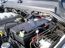
BCI Group 40R Deka 640RMF battery showing vent hose run forward to windshield washer reservoir area 1424 viewsRecessed post "Euro profile" battery to "match" OEM and stock Land Rover bracket; note that the Traxide SC80-LR module is mounted at an angle to allow for the main cable to sit under the cover so cover still closes.
The battery is a nominal 7", (180mm), high, but sits on a 1" battery spacer set under to raise the bottom front end of the battery such that the approx 11", (290 mm), length of the BCI 40R battery rises above the angled plastic nibs at the forward end bottom of the case front; hence sufficient space, (1/4", 5mm) remains at the brake reservoir end.
Also the 40R battery does not have hold down "flanges" on each end; on the sides yes, but not the ends so no additional length is required.
When I had to replace the 40R, this time I installed the shorter, (9.625"), taller, (7.5") Interstate BCI 47 / DIN H5 battery which eliminated the spacer on the bottom and better fit the stock LR tie down bolt lengths. Deka also has a BCI 47 / DIN H5 that would work fine as well.
|
|
Thread upload117 viewsImage uploaded in thread 69791
|
|
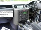
Bluetooth modules location1332 views
|
|

Black Deposits to interior of Brake Light Switch2831 viewsThere are two contacts, one on each side of the vertical plunger under the copper metal. The set of normally open contacts on the left side that carries the power for the brake light filaments, (15 amp fuse F15P), is apparently not heavy enough as the contacts deteriorate and generate the black residue.
The set of normally closed contacts on the other side appear to be sized OK. There is not as much current, (5 amp fuse F66P), flowing thru the contacts to the ABS module, however the contacts are likely adversely affected by the black residue produced by the other deteriorating set of contacts.
One presumes/hopes that the newer replacement switch now has contacts heavy enough to carry the brake light power. It would be ideal if the ABS set of contacts were sealed from the brake light contacts to prevent contamination of the normally closed set of contacts.
|
|

109 views
|
|

338 views
|
|
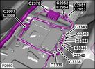
Camera Control Module D451 viewsHarness connection detail, camera module, located beneath L/H passenger side front seat UK D4 spec 2012.
|
|

77 views
|
|

CAN BUS MESSAGE14 viewsError I get when trying to read the Body Control Module Settings with my MSV2
|
|
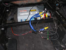
GVIf module under seat33 views
|
|
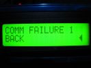
COMM FAILURE in the Faultmate FCR77 viewsThis is ONLY shown if either you have a communication error or in most cases you dont have fitted on your car the module you are trying to communicate with.
|
|

U013223 viewsLost Communication With Ride Level Control Module
|
|

U013225 viewsLost Communication With Ride Level Control Module
|
|

U015535 viewsLost Communication With Instrument Panel Cluster (IPC) Control Module
|
|

U015537 viewsLost Communication With Instrument Panel Cluster (IPC) Control Module
|
|
Under seat module148 views
|
|
86 views
|
|
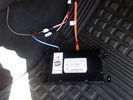
D4 Bluetooth AH42 10F845 AA module connected to 12VDC and MOST1190 viewsThis jpg shows the MOST bus connected to the AH42 10F845 AA module used in the D4 as well as +12VDC power from F58P connected. The power is split with a Y harness as the IHU (radio) for some reason required +12VDC power to the C2115-10 "mute" pin to keep the radio/CD audio from muting all the time.
With power on the pin, the radio audio does mute as it should when the cell phone rings and the hands free connects. The brown conductor feeds to C2115-10 and the blue to the module.
The module tucks up and hides behind the grey plastic section covering the forward portion of the passenger side tranny hump for left hand drive vehicles; for RHD, it would be located on the left side.
The pairing code is 2121 with this setup and not 1234 or 0000.
|
|

Thread upload9 viewsImage uploaded in new thread
|
|

Thread upload4 viewsImage uploaded in thread 150447
|
|
Thread upload11 viewsImage uploaded in new thread
|
|
module67 views
|
|
module connections107 views
|
|
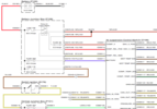
EAS_Module_Power16 views
|
|
117 views
|
|

Altox WBUS-4 Users Manual57 views
|
|

GX107 module with GPS unit and external aerial9 views
|
|
Thread upload0 viewsImage uploaded in new thread
|
|
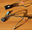
Heated Steering Wheels ECU's93 viewsEarly and Later Heated steering Wheel Control Modules
|
|
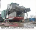
Messing with boats112 viewsShows our 300t capacity Lift System holding up an 80 tonnes module as the hull is winched underneath for final lowering and welding together.
|
|
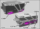
Base model IHU and High line IAM module connections83 views
|
|
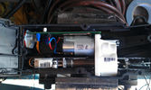
inside 2005 epb module115 views
|
|
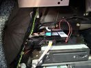
FFRR with d4 module184 views
|
|

FBH Main Modules21 views
|
|

First module - FBH Controller 21 views
|
|
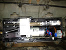
EPB Module Full92 views
|
|
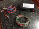
spare module22 views
|
|

led module55 views
|
|

led module land rover81 views
|
|

led boot space light upgrade95 viewsClose up showing how easy the led ultra bright modules fits into original housing
|
|
D4 Bluetooth modules 116 views
|
|
Bluetooth Faultmate MSV230 viewsPhoto of LM-048 Bluetooth module working with Faultmate MSV2
|
|

Transfer case control module29 views
|
|
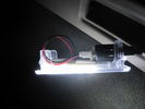
boot led module95 views
|
|
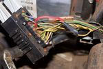
Can bus wiring repair18 viewsprevious owners repair to a can bus wire near the transfer case module
|
|

Prevoiuse driver seat in LHD now passenger seat base removed, memory module missing224 views
|
|
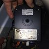
Nokia Bluetooth Module12 viewsLocated behind side panel of right hand luggage area. Connected to MOST system
|
|
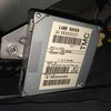
TMC Module11 viewsLocated behind side panel of right hand luggage area
|
|
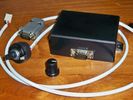
New switch182 viewsRotary switch and module box
|
|

LA100-004 - CAN Faults Relating to the ABS Module Diagnosis87 views
|
|

LA100-005 - Technical Bulletin - Internal Control Module Faults Relating to the ABS Module Diagnosis83 views
|
|

LA419-002 - Technical Bulletin - KIT Accessory Phone Module Fault72 views
|
|

LA501-021 - Technical Bulletin - Restraints Control Module Diagnostic Trouble Codes72 views
|
|

LR3 Denso Alternator YLE500390 pulley view817 viewsNote the DENSO sticker on the side. Denso calls their nominal 150 amp 12 Volt alternator an SC2 design. SC means Segment Conductor which apparently increase the winding density of the stator coil, hence yielding a physically smaller lighter alternator for a given output. I presume the 2 means the second try at getting it right. A Denso part number is 4280003690 for the alternator, (there are others, as below).
Rotation is clockwise and the 54mm diameter pulley has 6 grooves (PV6x54). Count the pulley grooves on both the one you remove and your new one - some replacement alternators seem to ship with 5 or 7 grooves so you might be swapping pulleys.
A previous LR part number was YLE500190 for the older variation of the newer YLE500390 unit.
An additional part number for a factory rebuilt is Nippon Denso 210-0569 for the petrol V8 alternator. Other Nippon Denso numbers include 104210-3690 and 104210-3691. The Lester number is 11206 which relates to another Denso number of 290-5287. WAI uses 11206N.
From 2006 to 2009, the internal regulator is a Transpo IN6349 and of the B circuit type if it can be said that applies to PWM, (Pulse Width Modulated), regulators.
The "regulator" inside the alternator is therefore really not a regulator in the old sense of the term but instead an instruction receiver from the ECM that translates Pulse Width Modulated (PWM) signals into a form that the alternator understands – digital like signals from the Engine Control Module(ECM) into analogue like signals that the windings understand.
|
|
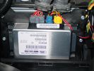
Thread upload0 viewsImage uploaded in thread 200528
|
|
Thread upload2 viewsImage uploaded in thread 200528
|
|

LTB00203 - Technical Bulletin - Driver Air Bag Module Trim Cover Distorted - Repair Procedure75 views
|
|

LTB00321 - Technical Bulletin - Restraints Control Module Diagnostic Trouble Codes113 views
|
|

module communication network39 views
|
|
113 views
|
|

314 views
|
|

234 views
|
|
Thread upload0 viewsImage uploaded in thread 195705
|
|
Thread upload0 viewsImage uploaded in thread 195705
|
|
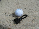
MOST fiber optic loop tool466 viewsThe looping tool in the jpg uses the Land Rover type plastic fiber optic cable with both ends feeding back into a female fiber optic connector that mates with the male fiber optic connectors on the Land Rover system.
The purpose of the loop is to allow one to disconnect MOST connected items such the BlueTooth module or the HK amplifier but allow the MOST system to still transmit signal from the head unit as the circuit would remain closed and hence complete. Of course with the Bluetooth module disconnected, there would be no Bluetooth available, however the radio and NAV would still function.
The looping tool allows one to troubleshoot the system by removing one component at at time from the MOST loop. In other words, what might appear to be a radio problem could be a Bluetooth problem - that sort of thing.
|
|

Thread upload13 viewsImage uploaded in thread 175320
|
|

How to cable factory BT module (including MOST bus connector)82 viewsInstructions to install Factory BT module in a Disco 3 that has LR aftermarket or no BT module installed
|
|

Thread upload8 viewsImage uploaded in thread 132008
|
|
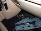
Location of old BT module48 viewsyou can pull out the module carefully
|
|
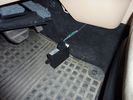
connectivity module57 viewsthis part is used for the aftermarket kit and will be removed
|
|
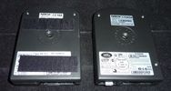
aftermarket and factory BT module52 viewsnotice the additional MOST connector (with white protective cap) for the factory install module
|
|
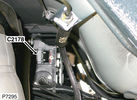
C2178 Module-Parking brake165 viewsPart No.: YPC801020
Colour: BLACK
Cavities: 32WY
Harness: CHASSIS HARNESS
Location: Beneath center of vehicle
|
|

PDC - Module Removal12 views
|
|

Thread upload9 viewsImage uploaded in thread 149479
|
|
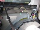
red is PDC sounder ...Yellow is PDC module 341 views
|
|

PDC Module25 viewsPDC Module mounted passenger side (RHD) rear door slam
|
|

PDC Module location30 viewsPDC Module located passenger side rear door slam (RHD)
|
|
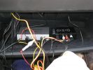
247 viewsThe two installed modules with preliminary wiring for testing.
|
|

Rear quarter panel removal171 viewsThe left hand side has the PDC module amongst others in it.
The one for the bluetooth module is the drivers side pannel.
|
|

Transpo pdf explaining the operation of Ford PWM regulators616 viewsThe 4 page pdf produced by WAI-Transpo explains the operation of the Pulse Width Modulated regulators located within the alternators on our 3's. Of note, the pdf states that certain of the Ford PWM regulators do not meet Ford spec.
The pdf explains the function of all the terminals and the apparent advantages of the PWM style over previous designs. Note that Ford calls their "engine computer" a PCM, (Power Control Module), whereas Land Rover, an ECM, (Engine Control Module).
|
|

Replacing the blower motor572 viewsThis is a 6 page pdf with regards to replacing the HVAC blower fan and the associated fan speed module in a LHD North America spec LR3. The fan can be replaced from below and it is not necessary to pull the dash apart.
|
|

Thread upload3 viewsImage uploaded in thread 193847
|
|
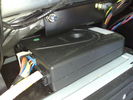
FFRR Nokia phone module26 views
|
|
Sounder Module fixed to body panel within LHS cubby hole195 views
|
|

Thread upload2 viewsImage uploaded in thread 193523
|
|
Telephone Module Settings32 viewsDisplay
|
|
![Filename=thumb_DSCN1852[1].jpg
Filesize=3KB
Dimensions=133x100
Date added=20.Apr 2014 thumb_DSCN1852[1].jpg](albums/userpics/33463/thumb_thumb_DSCN1852%5B1%5D.jpg)
rear audio in 31 viewsleft the D3 audio input socket
right freelander 2 video audio input module
|
|

Airbag module removal tool diagram504 views
|
|
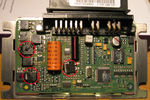
transfer case control module71 viewsPicture shows blown components of the Transfer Case control module after water ingress over time - with a healthy top up from over-enthusiastic lad with a high pressure water hose in the car wash!!!
|
|
Thread upload0 viewsImage uploaded in thread 188874
|
|

498 views
|
|
359 views
|
|
394 views
|
|
Thread upload12 viewsImage uploaded in thread 155591
|
|
Thread upload11 viewsImage uploaded in new thread
|
|
|
|
|
|