| Search results - "panel" |
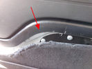
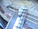
Rimozione pannello dalla sponda - Tailgate panel removing43 viewsPer togliere il pannello moquettato dalla sponda ho fatto leva con un cacciavite abbastanza grosso nel punto indicato, è stato veloce e non ho rovinato niente.
To remove the carpeted panel away from the tailgate I used a big enought screwdriver at the point indicated, it was fast and I have not ruined anything.
|
|

Climate control panel removal286 views
|
|

238 viewsThe roof panel (inside) with the internal bracket
|
|

148 viewsThe roof panel (inside)
|
|

132 viewsThe roof panel
|
|
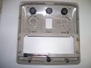
158 viewsRoof panel with the new switches
|
|
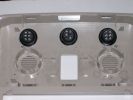
195 viewsSwitches installed in the roof panel
|
|
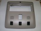
175 viewsSwitches in the roof panel
|
|
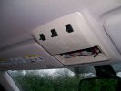
239 viewsPreview of the panel with the switches
|
|
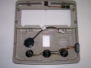
206 viewsRoof panel with wired switches and PTI microphone
|
|
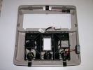
204 viewsRoof panel with switches, PTI microphone and bracket
|
|
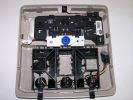
221 viewsThe complete roof panel reassembled
|
|
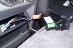
Centre console 12v & aux panel142 views
|
|
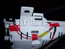
Insrument panel rear 31 viewsShowing wiring for heater and lights on indicator
|
|
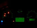
Insrument panel 33 viewsShowing heater and lights on indicator
|
|

instrument panel console removal258 views
|
|

Floor console upper panel removal211 views
|
|
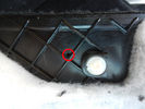
Foro pannello - Panel hole40 viewsHo forato il pannello moquettato per far passare il cavo di emergenza.
I drilled the carpeted panel to drive the emergency cable.
|
|
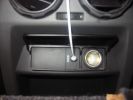
Centre console 12v & aux panel fitted278 views
|
|
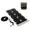
Thread upload7 viewsImage uploaded in new thread
|
|
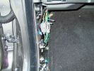
N/S Kickpanel wiring harness for AUX input4275 views
|
|

Inside the kickpanel4286 viewsRed = Left Channel
Blue = Right Channel
Black = Screen
|
|
Thread upload63 viewsImage uploaded in new thread
|
|
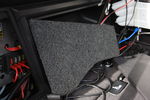
New cover for back panel63 views
|
|
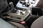
90 viewsLifted floor console upper panel to enable cubby box removal
|
|
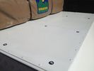
solar panels47 views
|
|
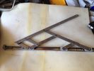
solar panels44 views
|
|
solar panels41 views
|
|
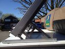
solar panels42 views
|
|
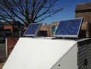
solar panels43 views
|
|
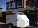
solar panels42 views
|
|
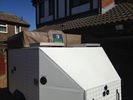
solar panels40 views
|
|
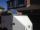
solar panels 46 views
|
|
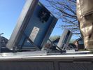
solar panels 41 views
|
|
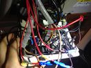
Roof Control panel24 viewsWell.. In reality it does not look as bad.. ;)
|
|
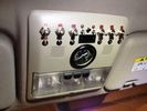
Roof Control Panel31 viewsThe "clean" side
|
|
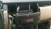
Yes, i am cutting the panel using a scissor...23 views
|
|
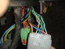
connector21 viewsLeft hand kick panel area
|
|
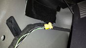
Plug behind rear quarter panel trim10 views
|
|
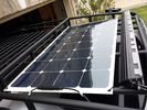
solar roof install437 viewsMore or less wrapped up my solar installation today. I added a Grape Solar Flex 100W panel, it's adequate to keep the vehicle topped off with the Fridge running, and Ham, but it could lose some ground if transmitting depending on how much, 2 would be awesome. One is enough, but barely. I am quite impressed with the Grape Solar flex panel version 2.0.
https://www.facebook.com/DifferentialPartsUS
|
|
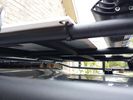
solar panel install347 viewsAt least at this point, I mounted it by using Clear Silicone RTV. This stuff is kind of like glue, but can be removed. If it doesn't hold up after curing and driving, I'll remove it and come up with another plan. I used heavy cable ties on the 4 grommets, in case it lets loose, it won't take out my wiring and the car behind me. 2 Panels are dandy like this, but I don't want to permanently block the roof space. Grape Solar to power my snomaster fridge
|
|
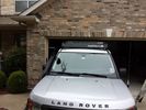
low profile solar panel203 viewsThe low profile solar panel, can be seen here, as the fine white line under the light bar. The way it's laid out, the panel should generate decent power between 10am and 4pm depending on the time of year, from the sides or front, with no shadows. Grape Solar 100W flex panel.
https://www.facebook.com/DifferentialPartsUS
|
|

Power Panel5 views
|
|
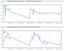
On Solar237 viewsOn Solar, Snomaster Fridge, Ham Radio and 100W Grape Solar panel, Deka 9A94R Intimidator AGM. I can supply the Stainless Snowmaster Fridges. Other components if you need help.
|
|

Front Door Trim Panel164 views
|
|

D4/LR4 501-12-floor console upper panel install instructions / german language64 viewsD4/LR4 501-12-floor console upper panel install instructions / german language
|
|

Rear Panel Complete96 views
|
|

Front Door Card23 views
|
|

Thread upload10 viewsImage uploaded in thread 183983
|
|

Rack61 views
|
|
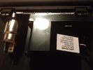
LR Aux Panel (rear)60 viewsBack of LR rear aux input panel
|
|
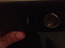
LR Aux Panel (front)68 viewsLR rear aux panel
|
|
173 views
|
|
176 views
|
|
189 views
|
|
190 views
|
|
198 views
|
|
184 views
|
|
185 views
|
|
187 views
|
|
312 views
|
|
336 views
|
|
287 views
|
|
246 views
|
|
231 views
|
|
Thread upload0 viewsImage uploaded in new thread
|
|
Thread upload0 viewsImage uploaded in new thread
|
|
Thread upload2 viewsImage uploaded in new thread
|
|
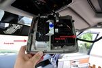
Roof panel dismount66 views
|
|

146 views
|
|

Thread upload9 viewsImage uploaded in new thread
|
|

Thread upload7 viewsImage uploaded in new thread
|
|
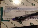
Aux Input Panel Box59 viewsCorrect Part Number
|
|
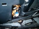
Brake Switch Visible thru Opening4933 viewsThe blue and white bit is the switch; the sort of gold appearing box,(it is really black), you will not see in your 3 as it is a Smooth Talker brand amplifier for my Blackberry phone antenna. This install is detailed in the SmoothTalker phone antenna section of my gallery.
One way to remove and install the switch is to lower the "horizontal" panel above the brake pedal as shown where the flashlight head is located. To actually remove the switch, you slide your hand thru the gap and rotate the switch clockwise 1/4 turn while watching thru the rectangular opening. Installation of the new switch is the reverse of above - 1/4 turn counterclockwise.
Before you remove the switch, note its orientation - horizontal with electrical wires to the left. That is the way it should look after replacement as well.
The second time I replaced the switch, I did it all thru the rectangular opening and did not remove the horizontal panel - that is experience helping out.
The knee kick you have to remove regardless. It is sort of hinged at the bottom so you just pull at the top and sort of rotate the knee panel and then pull upwards for two plastic "fingers" to clear the slots they reside in.
|
|
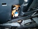
Smooth Talker Amplifier Box mounted below near steering column.179 viewsThe gold look box due to the lighting, (actually black), is the antenna amplifier located near the steering column. It can be put anyway but this seemed an OK location as I ran the antenna connector cable rearward from here to the back corner of the 3 and then up to the underside of the roof glass at the rear. The blue/white thing is the brake light switch that often must be replaced. See the Brake Light Switch file within this Gallery regarding the switch replacement.
|
|
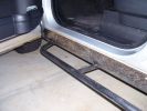
Sill protectors 2735 viewsThe side protection bar comes out a good 170mm. Prevents side panel damage and car-park knocks! Still deciding whether to fit the chequerplate tops, as originally designed.
|
|
Thread upload11 viewsImage uploaded in new thread
|
|
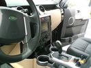
"H" panel after paint74 viewsPainted the vents and H panels and added some alu - nice change from the original look
|
|
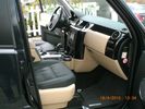
82 viewsPainted the H panel and the vents and got new lether seats - all in all a nice change to the original look
|
|
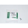
Clip Spring Metal FYC 500040 that holds LR together1744 viewsThe jpg is of the spring metal clip, Land Rover part number FYC 500040 that holds most of our 3 together - well at least most the interior trim parts.
If you are going to remove interior panels, you may as well stock up on a few for replacement as upon panel removal, the clips tend to spring away into deep never to be found voids within your 3.
|
|

Front Footwell Panel98 views
|
|

84 views
|
|

U015535 viewsLost Communication With Instrument Panel Cluster (IPC) Control Module
|
|

U015537 viewsLost Communication With Instrument Panel Cluster (IPC) Control Module
|
|

Thread upload11 viewsImage uploaded in new thread
|
|
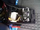
Rear view of panel17 views
|
|
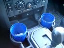
375 ml jam container369 viewsThese are the 375ml Danish Orchard brand jam containers. They fit fairly tightly into the original old style, (2005/6) Land Rover 3 factory cup holders. The extra height provided by the containers can be an advantage. I have a similar assortment of containers in some of the door panel located wine bottle holders to better hold containers of lesser valued products.
|
|
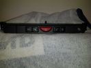
Thread upload0 viewsImage uploaded in new thread
|
|

100 viewsIf you leave a D3 in the water for too long, all the panels disolve and you find one of these underneath!
|
|

Nearside close up shot with boot trim removed250 views
|
|
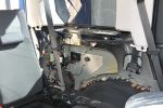
Nearside shot with boot trim removed288 views
|
|
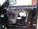
panel off 2569 views
|
|
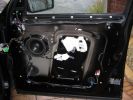
panel off495 views
|
|
clips on door panel474 views
|
|

Rear doors all working with new trim and panels removed60 views
|
|

Rear loading with panels removed60 views
|
|

585 views
|
|
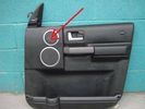
97 views
|
|

721 views
|
|
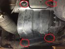
8 views
|
|
Kick Panel Corner5 views
|
|
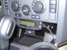
Ashtray panel replacement with ham radio rig.735 views
|
|
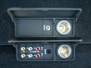
AVIO Panel118 views
|
|
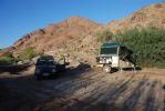
Solar panels being used 108 views
|
|
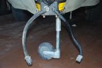
added battery connector for charging direct from vehicle - the solar panel also plugs in here, so can be used for vehicle or trailer charging104 views
|
|
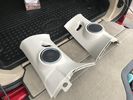
Thread upload7 viewsImage uploaded in thread 172989
|
|
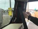
Thread upload7 viewsImage uploaded in thread 172989
|
|
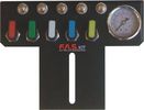
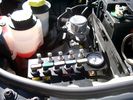
FASKIT air panel unmounted836 viewsThis is the manual air valve panel that is mounted in the "empty" space where the FBH normally resides. The gauge reads to a maximum of 25 Bar. The air tank relief valve is set just over 16.5 Bar (240 psig); the front air springs run maybe 9 Bar, (130 psig) and the rear, somewhat less, perhaps between 5 and 8 Bar. (70 to 115 psig). Max theoretical air spring pressure at full compression due to a big bump and full gross is approximately 27 Bar (390 psig).
|
|
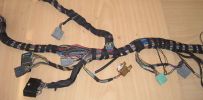
Finished Passenger Kick panel area123 viewsMissing connetor (left most grey) & wiring in, (plastic bracket was broke will use the one in the car) Airbag wires & connector to connector previously cut replaced (on top of grey one to right).
And you can even see the 2 new speaker wires going into the Pass door connector at the very bottom.
|
|

Floor Console Upper Panel102 views
|
|

Interior Trim468 views
|
|

Floor Console Upper Panel62 views
|
|

19 views
|
|
Thread upload2 viewsImage uploaded in new thread
|
|
Thread upload2 viewsImage uploaded in new thread
|
|
Thread upload10 viewsImage uploaded in new thread
|
|

How to swap front panel of HEVAC Unit62 views
|
|
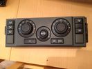
HVAC unit control panel30 views
|
|
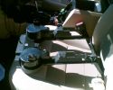
639 viewsCup holder panel showing the 8 locating lugs and clips
|
|
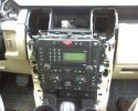
After removal of H-panel95 viewsCrikey, you have to pull HARD to remove this trim!!! Broke one clip and only lost half of it. Fit back with 3 clips ok. Yet to drive it to see if it rattles.
|
|
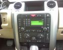
Before removal of H-panel73 views
|
|
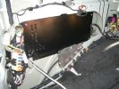
944 viewsFitting a 1500Watt 220v Inverter Behind the rear LH side panel.
|
|

2035 viewsEverything pulled to bit\'s in order to get cables in for PC Screen etc.
Note the panel with USB and LAN connectors on, this replaces the LR panel with the ash tray in.
|
|

2268 viewsAll back together again, note the connector panel below the heater controls, it has USB and LAN connections for the Onboard PC
|
|
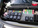
Picture of the engine compartment fuse panel5752 viewsEngine compartment fuse panel located near the battery. This is where F3E, (5 amp), F26E, (20 amp), Fuseable link 10E, (60 amp) and Relay 7E, the now upgraded 70 amp air compressor motor relay, part number YWB500220, (E is for Engine compartment fuse box), are all located. Fuse F35P, (5 amp), is inside the Passenger compartment behind the lower glove box door.
To keep the suspension from going down to the stops when driving, (or parked), it appears that it is only really necessary to remove F26E to depower the exhaust valve and generally keep all the valve block solenoid valves in a closed position trapping whatever air is within the air springs. F3E gets its power thru F26E, so when F26E is removed, the F3E circuit is automatically de-powered. F35P is more interesting in that battery power goes thru the ignition switch and F35P and then into the air suspension control unit. Apparently however, if F26E is removed, removing the F35P is not needed even when the engine is running.
With all fuses still in, if you have a problem, in practice, ideally, the compressor still works and will raise the 3 to an appropriate height. If so, one can then shut the engine off and allow the computers to go to sleep and then you remove the fuse(s). In actual practice, it seems that one need only pull the F26E fuse and can do so with the engine running. All the same, one might consider that the 3 is first a mobile computer, and secondly a 4x4. Computers prefer to go to sleep before the plug is pulled on them, however given that F26E circuit is always alive, then the computer never sleeps. With the fuse(s) pulled, and if you are still up, you can now be a 4x4 instead of a low rider. The whole purpose of the fuse pulling exercise is to depower the one and only system exhaust valve that is physically located within the compressor unit, (to keep it from opening), and secondarily to keep closed the four air spring solenoids within the block valves. This also shuts the air compressor down and stops the air compressor from making air even if the compressor is still good. That is why you initially need the fuse(s) in to allow the compressor to make air if it can.
|
|

Switch is blue colour thing thru the rectangular opening.3149 viewsThe blue coloured plastic bit thru the rectangular opening is the brake light switch. The fist time, I found it easier remove the switch by dropping the horizontal plastic panel, (two screws), and then slipping my hand in and rotating the switch clockwise 1/4 turn. The second time, I was able to remove the switch thru the rectangular opening and did not need to remove the horizontal lower panel. Obviously, I had to remove the sloping knee pad panel, (note sort of hinged at the bottom so pull back from the top.)
Regardless, do not touch the brake pedal - just let it sit where it wants to. One has to first remove the angled knee pad panel that sits under the steering wheel. It can be pulled from the top corner at the door side. Pulling releases a pair of those U shaped metal clips that LR loves so dearly. You have to pull quite hard. The bottom is held by a couple of plastic fingers in a couple of slots so you pull at the top till the two clips release and then rotate the panel and pull upwards a bit.
To remove the switch, you rotate it clockwise and pull outwards. Rotating the switch clockwise automatically retracts the plunger back into the switch body away from the brake pedal arm.
Similarly when you install the new switch, the required 1/4 turn anti clockwise rotation action releases the plunger so it lays up against the brake pedal arm and at the same time, secures the switch in place.
To remove the electrical wires, the switch will drop below the horizontal pad and hang from the wires so unclipping the electrical connector plug is fairly easy to do.
|
|

drilling holes into cubby box for AV connection panel50 viewswork in progress
|
|

boot panel97 views
|
|

PP002 12V128 views Brad Harris Socket
Hella Socket Cigarette
Lighter Socket
Battery Level Meter
External Terminals for Battery Charger or Solar Panel
ON/OFF isolator tie down strap excludes Battery
Built in fuses
https://www.facebook.com/snomasterusa
|
|

scuttle panel 115 views
|
|

A nice piece of kit...349 viewsOne piece of kit I bought for myself. A backpack big enough for one of those 17" MacBook Pro from Apple which does also possess some solar panels to recharge the batteries in my Treo, my BT GPS or iPod. Convenient for when I am NOT in the car... Here the background is an armored Toyota... No Landies around ! :-(
|
|
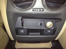
AUX Panel56 views
|
|

AUX Panel plug56 views
|
|

AUX panel plug56 views
|
|
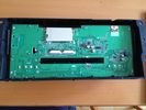
Back view of front panel removed from head unit with facia still attached15 views
|
|
plastic inspection panel lower right weelarch45 views
|
|
H trim Panel & Side Vents Being High Build Primer88 views
|
|

UHF Antenna Mount384 viewsView from underside of bonnet. The lower half of the mount is folded from stainless steel and bolted through an exisitng oval shaped hole in the bonnet. This hole is throught the heavy steel plate that the bonnet hinges bolt to - not just the aluminium panel. A specially machined rectangular nut was made to pass through the oval hole, rotate 90 degrees and then stopped from turning by a slight shoulder on the nut.
|
|

Mobile Phone antenna mount342 viewsView of mount with bonnet open - note stick on patch to protect plastic panel at base of windscreen
|
|
Nokia Bluetooth Module12 viewsLocated behind side panel of right hand luggage area. Connected to MOST system
|
|
TMC Module11 viewsLocated behind side panel of right hand luggage area
|
|
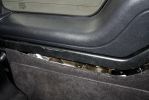
105 viewsCarpet panel pried away from tailgate trim
|
|
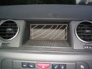
Dashboard625 viewsWhat is behind this panel
|
|

instrument cluster and panel illumination48 views
|
|

instrument panel and console43 views
|
|

Instrument Panel Blend Door Actuator14 views
|
|

instrument panel speaker.JPG190 views
|
|
Thread upload13 viewsImage uploaded in thread 164172
|
|

7 views
|
|
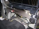
off side rear panel removed958 views
|
|
off side rear panel removed879 views
|
|

LAND ROVER DISCOVERY 3 istruzioni rimozione pannello porta posteriore Rear Door Trim Panel Removal 7E0183 viewsLAND ROVER DISCOVERY 3 istruzioni rimozione pannello porta posteriore Rear Door Trim Panel Removal 7E0
|
|

LAND ROVER DISCOVERY 3 istruzioni rimozione pannello porta posteriore Rear Door Trim Panel Removal 7E0112 viewsLAND ROVER DISCOVERY 3 istruzioni rimozione pannello porta posteriore Rear Door Trim Panel Removal 7E0
|
|

Harness that connects inside left rear compartment.435 viewsThis is the harness section that connects behind the left rear interior access panel and exits thru the large grommeted hole to below/behind the left rear tail light.
Note the two rubber grommets on the harness as there is both an interior metal skin and an exterior metal skin behind the left tail light assembly.
The two light grey connectors plug into two existing connectors near the top of the rear left interior access panel. The two darker connectors plug into the second piece of harness.
There is no little separate fuse box either with the NAS spec harness. The fuse box is included with the UK 13 pin dual plug units. If there was a fuse box, it would be on this portion of the harness.
|
|
Thread upload13 viewsImage uploaded in thread 99905
|
|
Thread upload23 viewsImage uploaded in thread 141004
|
|

Littelfuse Add-A-Circuit MINI and ATO style data sheet148 viewsPDF from Littelfuse showing both the MINI and ATO style of fuse holders. The 3 uses the MINI size of fuse. The MINI Add-A-Circuit can be inserted in place of one of the existing fuse panel MINI fuses. The removed fuse is then inserted into the lower slot of the Add-A-Circuit and a second fuse in the second slot to protect the device that you are adding. The Add-A-Circuit is designed for a max of 10 amps on the second load, and I guess maybe the original circuit as well.
|
|
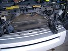
19mm wiring loom in trough behind bumper and in front of rad790 viewsThe 19mm wiring loom is large enough that a maximum of six 6mm air lines can be fished thru as required. The loom runs from the FASKIT panel located in the engine compartment behind the left front headlight, down and across in front of the rad and then down to the front axle valve block located behind and below the right fog light.
|
|
370 viewsHere is the left rear trim panel removed. GTR proved useful in the removal process! The cubby box snaps on to the top of the panel.
|
|
458 viewsCompleted install of control panel.
|
|
388 viewsCompleted Install of Control Panel. Wiring goes up into headliner, over curtain airbag on left hand side, and down the B pillar.
|
|
Boot lighting panel, finish side up 307 viewsThe above jpg shows the two 15 LED light assemblies as well as the SPST rocker switch mounted beside the W5W Land Rover supplied light.
The reality is that with the recent development of LED lighting that can replace a W5W T10 bulb, one can almost achieve the same results just by installing a LED bulb within the factory light.
|
|
Boot lighting panel, wiring side up 279 viewsThis shows the back side of the plastic cover panel on which the two LED lights are mounted.
Also of note is the SPST rocker switch to switch the new lights off independent of the the Land Rover W5W light.
The new light pair will only power up if the Land Rover light is powered and hence dims and automatically goes off along with the Land Rover light.
The Black wire is ground, the Purple wire is +12VDC.
|
|
View of mounted panel from front left side872 viewsNote that all valve handles are shown in the OFF position, (the trouble position). In this case, the air that is in the air springs, (if any), is trapped in there - that is the valve blocks cannot vent whatever air is already in the air springs as the air lines between the springs and respective valve blocks are closed off by the FASKIT valves. In operation, there may be only trouble with one air spring, (perhaps a wheel height sensor), and as such, only one valve would need to be closed. If there was complete air compressor failure, then all valves would be closed and then as required, each spring could be manually filled from an outside clean dry oil free air source.
|
|
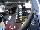
View of mounted panel from front left corner732 viewsI drilled a hole for the supplied 6 mm tie down toggle bolt in a flat portion of the wing on which the panel sits. I inserted a 50 mm flat rubber washer between the wing metal surface and the underside of the black painted panel plate; also a 40 mm flat rubber washer between the supplied fender washer and the metal plate - just seemed like a good idea so surfaces mate well even if wing metal not completely flat.
|
|
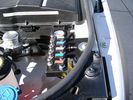
View from front left side looking towards rear aux battery compartment under cover 643 viewsAs there is no Fuel Burning Heater in the NAS V8 petrol vehicles, there is space available to install the FASKIT panel here. The piping is such that each air spring can be isolated from the air system and then filled one at a time manually via the Schrader valve. There are five Schrader valves and five shutoff valves. The fifth valve nearest the gauge controls air from the compressor, and can provide fill up air via a jumper fill line assuming the compressor is still operational.
|
|
Empty space in NAS LR3 for location of FASKIT panel595 viewsThe empty space is available as the North America Spec gasoline engine LR3's do not have the Fuel Burning Heater installed. The air lines from the four air springs and the air tank will appear to rise up from under the headlight assembly. The lines to the front block valve assembly located behind the front right fog light will sort of run within the bumper across the front of the radiator down into behind the righthand fog light. The rear lines somewhat follow the path of the existing air feed line from the front valve assembly to compressor. Rather than be located between the left front fender liner and left metal wing however, the four lines will feed thru the empty wing space inside and above the wheel well arch and exit down by the left front mud flap. From there, the lines run along the left frame member above the air tank and then parallel the frame over top the compressor to the top of the rear left air spring where the rear air block valve assembly is located.
|
|

Carpet Panel Removed showing Bass Speaker and Dust Shield 1722 viewsSomething is wrong with the orientation, however this shows what you see when the carpet is removed.
The dust shield, (under which the actuator is located), in the picture is as yet uncut. The white bit is the underside of the plastic lower lift gate carpeted cover panel.
The round thing is the woofer speaker for the Harmon Kardon radio. When the radio is working, one can see the speaker moving, but not much bass sound actually seems to emanate from the speaker.
|
|
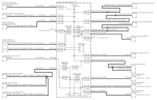
Power Window Circuit centered on Central Junction Box (behind glove box fuse panel)726 viewsRelay 143, the power window relay, and most other relays and FET's as well are built into the back of the passenger side behind the lower glove box fuse panel.
As such, the relays etc are not removable, jump-able, or serviceable.
|
|
19 mm wire, (tubing), loom rising from below at left headlight653 viewsFrom the FASKIT panel, five air lines fit in the 3/4" (19mm) wiring loom and feed to the front air valve block located behind and under the right front fog light.
|
|
Wiring (tubing) loom at left headlight showing FASKIT panel 582 viewsThis shows the wiring (tubing) loom and FASKIT panel mounted to left wing. The loom moves a a couple of inches (50mm) towards the bottle once the headlight is put back in as there is not enough free space for the loom as located. The FASKIT panel is just visible at the top left corner of the picture.
|
|
Wiring, (tubing), loom exiting temporarily from the front right fog light.566 viewsThe front axle air valve block is located just behind and below the fog light. Access to the valve block is by removing the right front fender liner, (or the bumper). The FASKIT lines are attached to the left and right front air spring lines at this location; also compressor air is taken from this location as well. Cutting the lines at as few different locations makes it easier to find leaks at a later date. As above, five 6mm air lines run from the FASKIT panel to the front axle air valve assembly and run within the loom. Two pair of the lines are for control of the air springs, and the fifth line taps the air supply at the valve block assembly off the compressor. This will be the air source line rather than tapping in directly to the high pressure air tank.
|
|

we put the fuses in the rear panel as well as the air tank gauge, air switch, and battery switch.411 views
|
|
a few items being built in behind cover panel.435 viewsred inverter will have fluch mount plugs, air outloet will be flush, guage with window in lower pop-panel and switches and fuses for all rear items behind popout panel.
12v sockets being added as well, high and low.
|
|

LR3 Brake Wear Sensor Wiring1489 viewsThis 1 page wiring diagram pdf shows that both the front and rear brake pad wear sensors are part of a closed series circuit to ground.
In operation, when all is good, the series circuit is grounded and the amber brake wear warning indicator on the instrument panel is not illuminated.
When the pads on one wheel, either the left front, or right rear, become too worn, the respective sensor is "cut" which results in an open circuit condition. This causes the dash brake wear indicator to illuminate.
The circuit is like the old style Christmas light strings where one burned out bulb caused the whole string to go out.
A quick field fix to get the dash light to extinguish in lieu of replacing the sensor and pads etc is to disconnect the brake pad wear sensor and short across the two open conductors of the vehicle side connector plug. This of course means you now have a normal vehicle, one of the thousands that do not feature brake pad wear information systems.
|
|

LTB00084 - Technical Bulletin - Glass Roof Panel Blind Difficult to Latch - Repair Procedure136 views
|
|

LTB00218 - Technical Bulletin - Water Leak into Footwell From Roof Opening Panel Drain Tube97 views
|
|
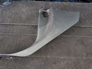
Magnetic Panels100 views
|
|
Thread upload2 viewsImage uploaded in new thread
|
|
Thread upload0 viewsImage uploaded in new thread
|
|
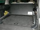
Sliding floor - in closed position with floor panel open to gain access to tools, etc.494 views
|
|
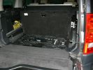
Sliding floor - in closed position with floor panel open to gain access to tools, etc.473 views
|
|

Cowl23 views
|
|

Thread upload0 viewsImage uploaded in thread 185212
|
|
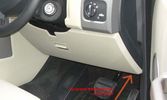
95 views
|
|

Thread upload0 viewsImage uploaded in thread 184905
|
|

Thread upload0 viewsImage uploaded in thread 185224
|
|

Thread upload0 viewsImage uploaded in thread 184905
|
|

Thread upload0 viewsImage uploaded in thread 184905
|
|
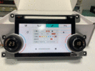
Thread upload6 viewsImage uploaded in thread 199389
|
|

Thread upload0 viewsImage uploaded in thread 184905
|
|

Thread upload0 viewsImage uploaded in thread 185212
|
|
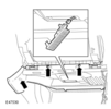
Thread upload17 viewsImage uploaded in thread 102539
|
|
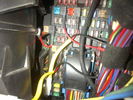
Fuse Panel showing F35P Add A Circuit installed1230 viewsFive amp fuse F35P is located towards the top left in this jpg. The other three Add A Circuit devices are for other items - powering my cell phone base etc.
Note the orientation of the Add A Circuit as this matters. Also one can just see a red tab sticking out from behind the device. The red is the conductor crimp end of a narrow 2.8mm male spade type connector that inserts into one of the "fuse" slots.
|
|
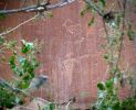
77 viewsPetroglyph panel
|
|

106 viewsGreat sylized antelope in this petroglyph panel, and some sort of cyclops snake with antennae.
|
|
Panel gap421 viewsthis is the offending poorly fitted plastic capping
|
|
256 viewsSystem testing. Nothing caught fire, which is a success in my book! Just know that the rover gets very angry when all of those control panels are disconnected.
|
|
panel removed plugs visible350 views
|
|
Removed side panel - 4 plastic plugs pulls off easy324 views
|
|
remove metal clips from floor panel and reinstall on to the plastic trim293 viewsIf you leave the clips in place and try to force the trim back in the clips are knocked through the floor unit and it takes an hour to get them out!!
|
|
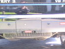
camera all installed - same size as a sensor381 viewscant go in centre of panel due to towing hoop
|
|

Thread upload6 viewsImage uploaded in thread 174151
|
|

6 views
|
|

199 views
|
|

Rear Door Trim Panel Removal.pdf627 views
|
|

74 views
|
|

Rear Door Trim Panel Removal426 views
|
|
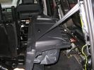
Offside rear panel party removed104 views
|
|

Rear end164 views
|
|

Rear Quarter Trim Panel Removal419 views
|
|

Rear quarter panel removal171 viewsThe left hand side has the PDC module amongst others in it.
The one for the bluetooth module is the drivers side pannel.
|
|

Rear Quarter Trim Panel Removal354 views
|
|

Rear Quarter Trim Panel83 views
|
|

Removing rear panel87 views
|
|

14 views
|
|
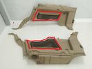
Thread upload3 viewsImage uploaded in new thread
|
|
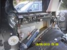
Thread upload18 viewsImage uploaded in new thread
|
|
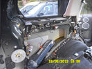
62 views
|
|

Rear Quarter Trim panel19 views
|
|

23 views
|
|

107 viewsRear Quarter Panel Removal
|
|

Removal of C-Pillar Lower Trim84 views
|
|

Rhino rack and Oztent RV3125 viewsI needed a 3rd Rhino aero sports bar in order to support the Oztent RV3, self-inflating mattress, and Oztent side panels/front.
|
|
Right Rear quarter panel removed61 views
|
|
LHS rear quarter panel59 viewsThis is what it looks like behind my vehicles rear quester panel
|
|

Scuff Plate Trim Panel78 views
|
|

Scuff Plate Trim Removal15 views
|
|
9 views
|
|
Thread upload10 viewsImage uploaded in thread 141119
|
|
Sounder Module fixed to body panel within LHS cubby hole195 views
|
|
Thread upload2 viewsImage uploaded in thread 40682
|
|
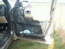
TazDaz door panel after unfortunate splashing incident161 views
|
|
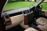
155 views
|
|
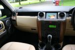
155 views
|
|
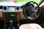
176 views
|
|
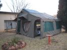
Trailer tent175 viewsHowling Moon trailer tent, approx 4.9 x 4.9 meters, with front extension
and side panels.
|
|

Thread upload14 viewsImage uploaded in thread 116740
|
|

11 views
|
|
Thread upload0 viewsImage uploaded in thread 186484
|
|
|
|