CarPC Installation |
 |
| TITLE |
+ |
- |
| FILE NAME |
+ |
- |
| DATE |
+ |
- |
| POSITION |
+ |
- |
|
|

81 viewsStarting point
|
|

74 viewsRemoved console surround trim
|
|
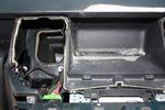
85 viewsDrilling a hole in the rear part of the floor of the dash pocket for the cables to go through
|
|
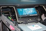
108 viewsTest fitting the screen. The bottom edge of the rear cover of the screen has been already dremeled off in this pic, notable as the circuit board can be seen.
|
|
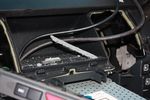
94 viewsCutting a trench in the dash pocket floor to wedge the bottom edge of the screen into
|
|
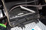
89 viewsCutting the trench in the dash pocket.
|
|
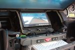
105 viewsScreen in place.
|
|
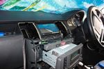
95 viewsScreen in place
|
|
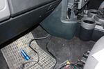
88 viewsCables out into passenger footwell
|
|
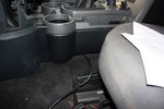
92 viewsStuffing cable under the floor console
|
|
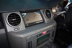
96 viewsScreen in place
|
|
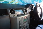
98 viewsScreen in place and console surround back on
|
|
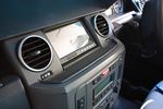
95 viewsCut the original rubber mat to fit flush with the screen
|
|
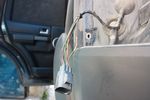
94 viewsReverse wire stripped. I then soldered the wires which I need to this wire and close up with self amalgamating tape. This way I don't damage any original wires (except for the insulation) and it's easily reversible by desoldering
|
|

82 viewsReverse wire tapped into
|
|

78 viewsThrough the vents into the D-pillar
|
|
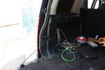
77 viewsAt the D-pillar
|
|

94 viewsOut at the C pillar. From here wires were threaded through the rear seatbelt anchor point into the commercial box, which is the hub of all the wiring and CarPC installation
|
|
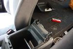
76 viewsRemoved cubby box lid
|
|
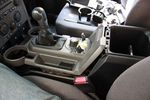
90 viewsLifted floor console upper panel to enable cubby box removal
|
|
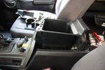
70 viewsCubby box coming out
|
|
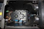
75 viewsInside the cubby box
|
|
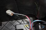
108 viewsThis is the plug for the accessory socket at the rear of the cubby box. On commercial D3 such as this one, there is no accessory socket so this plug is unused. I tapped into the 12V wire as an ignition feed. This will feed a relay coil which opens up power from the aux battery. Like this I can still retro fit and make use of the accessory socket later on.
|
|
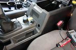
76 viewsDrilled hole for switch
|
|
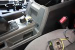
76 viewsSwitch in place
|
|
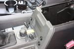
98 viewsAll 4 switches in place.
Driver's side switches are:
. Parking sensors master switch
. Reverse camera off/on/reverse-tiggered
Passenger side switches are:
. CarPC off/on/ignition-triggered
. 12V Regulator off/on/ignition-triggered
|
|
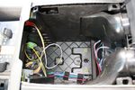
73 viewsStarting the switch wiring
|
|
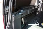
78 viewsHole for 12V accessory socket. This hole has a blanking plate on it on Commercial D3s. It just needed to be filed down in some areas to fit the socket I bought.
|
|
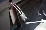
72 viewsWiring for 12V socket attached to socket
|
|
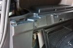
91 views12V socket done. This is permanently powered by the Aux battery. Another one was done on the other side, though that one required drilling the hole with a 29mm hole saw as there wasn't an unused hole on that side.
|
|

76 viewsBench testing the CarPC
|
|
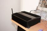
83 viewsCarPC closed
|
|
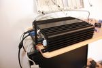
79 viewsCarPC closed and ready for mounting. Note the modification to the rear of the case to allow extra USB sockets attached to the motherboard pins.
|
|
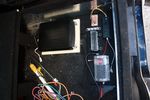
96 viewsDeciding on a layout for the electrical stuff. Bottom right of pic is a fusebox which will take the input power from the traxide kit, then relay box and 12V regulator, ignition busbar and homemade regulated 12V busbar. Big black box is the CarPC
|
|
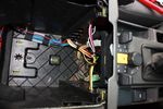
70 viewsAll switch wiring neatly routed to exit hole
|
|
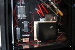
77 viewsElectrical items fitted in place and wiring in progress
|
|

67 viewsJungle of wires coming out of the cubby box
|
|

63 viewsCables grouped together and routed neatly. Cable sleeving can be seen cable tied to the VGA screen cables at this point
|
|
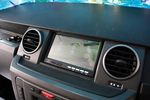
116 viewsCarPC running
|
|
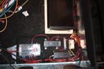
75 viewsAll wired up!
|
|

78 viewsExtra USB sockets mounted to front of commercial box, just behind cubby box
|
|
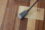
63 viewsCut a slot in the socket grip to fit the cutout
|
|
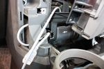
62 viewsCutout done, all that's left is to stuff the socket into the cutout
|
|
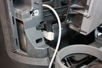
69 viewsUSB socket finally wedged in place. Cable routing will take the same route as VGA screen cables
|
|
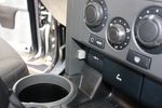
86 viewsAll back in place. Front USB socket final result.
|
|
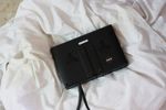
66 viewsScreen originally, with wires out the bottom
|
|
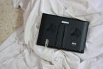
69 viewsRear cover off, slot dremeled into cover. I also had to cut off the entire bottom edge off the cover at a later stage for it to fit comfortably in the dash pocket.
|
|
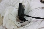
66 viewsScreen now with wires out the rear end
|
|
|
|